Method for overcoming poor shunting of track circuit

A technology for poor track circuit and shunting, which is applied in the direction of power lines, railway signals, railway car body components, etc., can solve problems such as poor track circuit shunting, damage to signal interlocking relationships, and hidden safety hazards of driving accidents, and achieve the goal of overcoming track problems. The effect of bad circuit shunting

Active Publication Date: 2012-11-21
CHINA SHENHUA ENERGY CO LTD +1
View PDF4 Cites 6 Cited by
  • Summary
  • Abstract
  • Description
  • Claims
  • Application Information

AI Technical Summary

Problems solved by technology

[0004] For the existing track circuit, due to the formation of a rust layer on the rail surface in the track circuit section where the train does not normally travel, the contact resistance between the wheelset and the rail increases when the train passes through

Method used


Image

  • Method for overcoming poor shunting of track circuit
  • Method for overcoming poor shunting of track circuit
  • Method for overcoming poor shunting of track circuit

Examples


Embodiment Construction

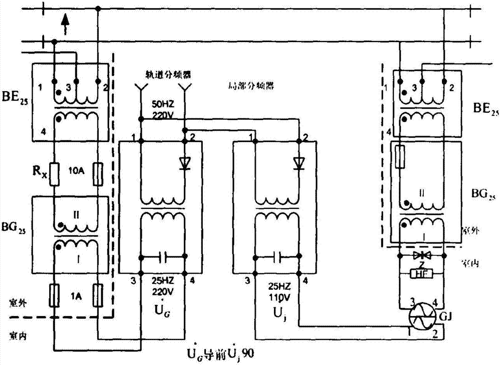
[0020] In the following, the method for overcoming the poor shunt of the track circuit according to the present invention will be described in detail with reference to the accompanying drawings.

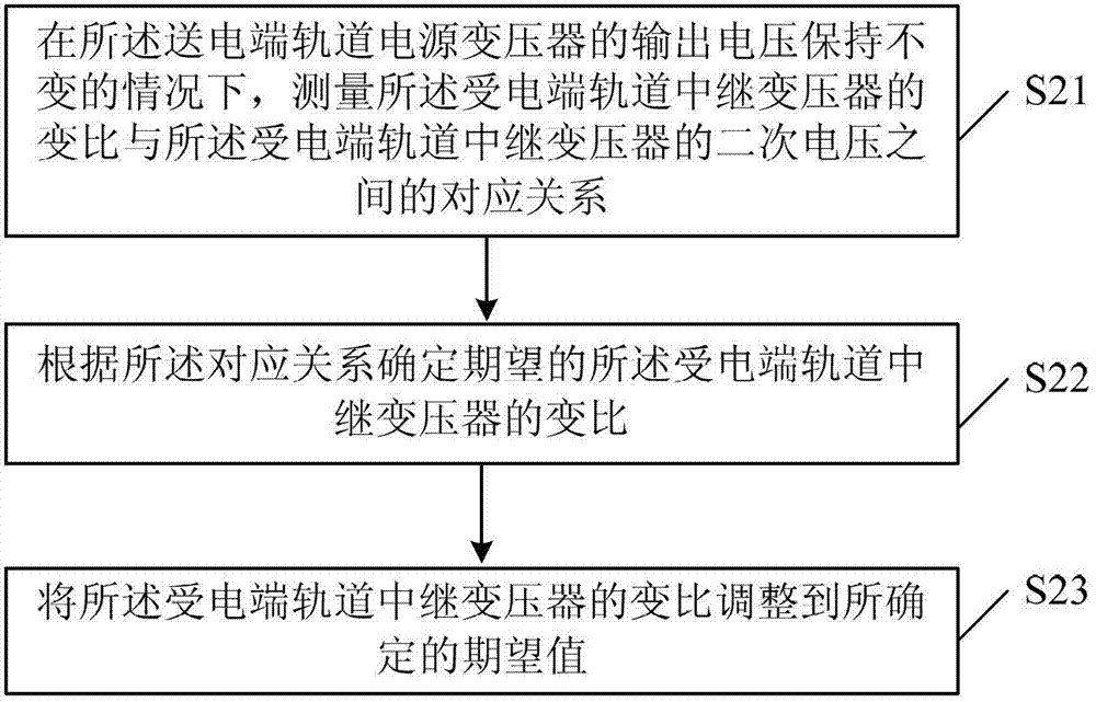
[0021] Such as figure 2 As shown, the method for overcoming the poor track circuit shunt according to an embodiment of the present invention includes the following steps:

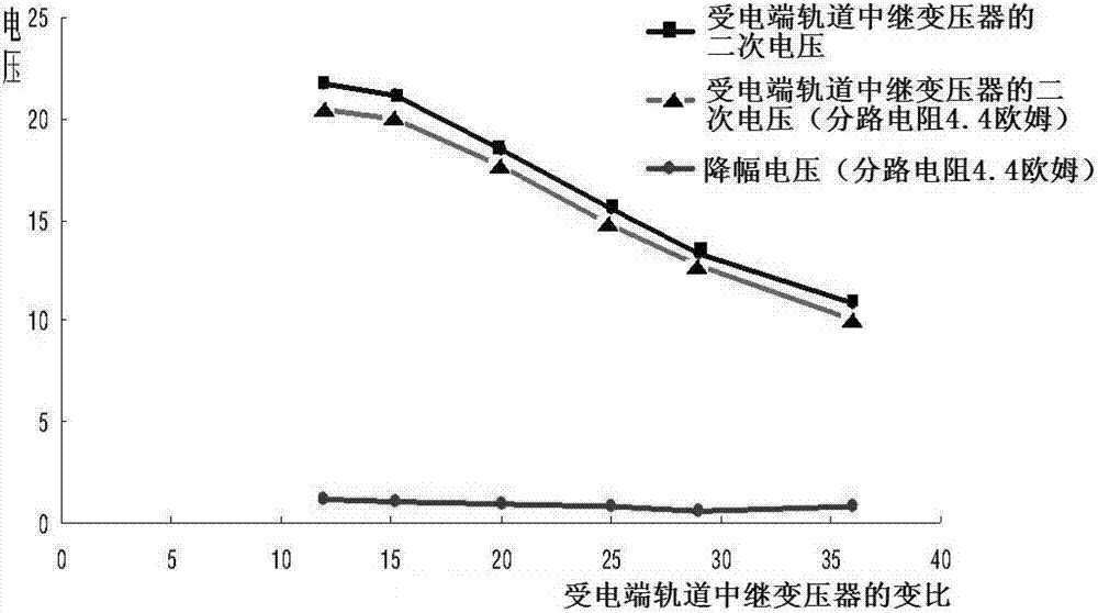
[0022] S21. Under the condition that the output voltage of the track power transformer at the transmitting end remains unchanged, measuring the transformation ratio of the track relay transformer at the receiving end and the secondary voltage of the track relay transformer at the receiving end Correspondence;

[0023] S22. Determine the desired transformation ratio of the track relay transformer at the receiving end according to the corresponding relationship;

[0024] S23. Adjust the transformation ratio of the track relay transformer at the receiving end to the determined desired value.

[0025] The above method of the ...


PUM


Abstract

The invention provides a method capable of effectively overcoming poor shunting of a track circuit, aiming at the defect that poor shunting of the track circuit can not be effectively overcome after once-for-all adjustment is conducted according to Railway Signal Maintenance Rules in the prior art. The method comprises the steps of: 1) under the condition that the output voltage of a track power supply transformer at a feed end is kept unchanged, measuring a corresponding relationship between the transformation ratio of a relay transformer in a track at a receiving end and the secondary voltage of the relay transformer in the track at the receiving end; 2) determining a to-be-expected transformation ratio of the relay transformer in the track at the receiving end according to the corresponding relationship; and 3) adjusting the transformation ratio of the relay transformer in the track at the receiving end to the determined to-be-expected value.

Description

Technical field [0001] The invention relates to the field of railways, in particular to a method for overcoming the poor shunting of track circuits. Background technique [0002] Currently, track circuits are generally used in China to detect the occupancy of train track sections. Generally, the existing track circuit can be divided into the power transmitting terminal, the power receiving terminal with a choke transformer, and the power transmitting terminal and the power receiving terminal without choke according to whether the power transmitting terminal and the power receiving terminal are equipped with a choke transformer. There are two types of current transformers; according to the setting of the receiving end, it can be divided into three types of track circuits: one sending and one receiving, one sending and two receiving, and one sending and three receiving. [0003] figure 1 It is a typical circuit diagram of a 25Hz phase sensitive track circuit with a choke transformer...

Claims


Application Information

Patent Timeline
IPC IPC(8): B61L1/18B60M3/00
Inventor 赵彦星
Owner CHINA SHENHUA ENERGY CO LTD
Why Eureka
Try Eureka