Quenching waste gas heater of coal pyrolyzing furnace

A coal pyrolysis and heater technology, which is used in the heating of coke ovens, combustible gas heating coke ovens, coke ovens, etc., can solve the problems of low production efficiency, no waste gas export, recovery and purification, and inability to carry out continuous production. , to achieve the effect of reducing the cost of coking

Active Publication Date: 2014-04-30
山西睿得新材料科技有限公司
View PDF4 Cites 0 Cited by
  • Summary
  • Abstract
  • Description
  • Claims
  • Application Information

AI Technical Summary

Problems solved by technology

[0002] Most coal pyrolysis furnaces (coke ovens) currently on the market adopt batch-type coking. Coke upgrading, dry quenching and other process steps are relatively independent, continuous production cannot be carried out, and production efficiency is low; in addition, the raw coal gas generated during coal pyrolysis contains many useful components, such as H2S , HCH and other acid gases, NH3 basic gas, tar, benzene, naphthalene, washing oil and other organic substances, there is no complete process for exporting, recycling and purifying raw gas

Method used


Image

  • Quenching waste gas heater of coal pyrolyzing furnace
  • Quenching waste gas heater of coal pyrolyzing furnace
  • Quenching waste gas heater of coal pyrolyzing furnace

Examples


Embodiment Construction

[0029] The specific embodiment of the coke quenching waste gas heater of the coal pyrolysis furnace of the present invention is mainly introduced in detail in the first section of the fourth part below.

[0030] Part 1 Furnace Coal Proportion and Preparation

[0031] If 5 different coals are selected, they are respectively gas coal, fat coal, coking coal, one-third coking coal, and lean coal, which are first mixed and then sieved and crushed until the broken particles reach below 5mm to form the furnace coal. Of course, the coal of the present invention is heated The decomposing furnace is equally applicable to other proportions and particle sizes of the furnace-feeding coal, and does not constitute a limitation to the furnace-feeding coal powder required by the coal pyrolysis furnace of the present invention.

[0032] The second part of coal dehydration

[0033] The incoming coal entering the coal pyrolysis furnace is dehydrated in advance through the incoming coal dehydrati...


PUM


Abstract

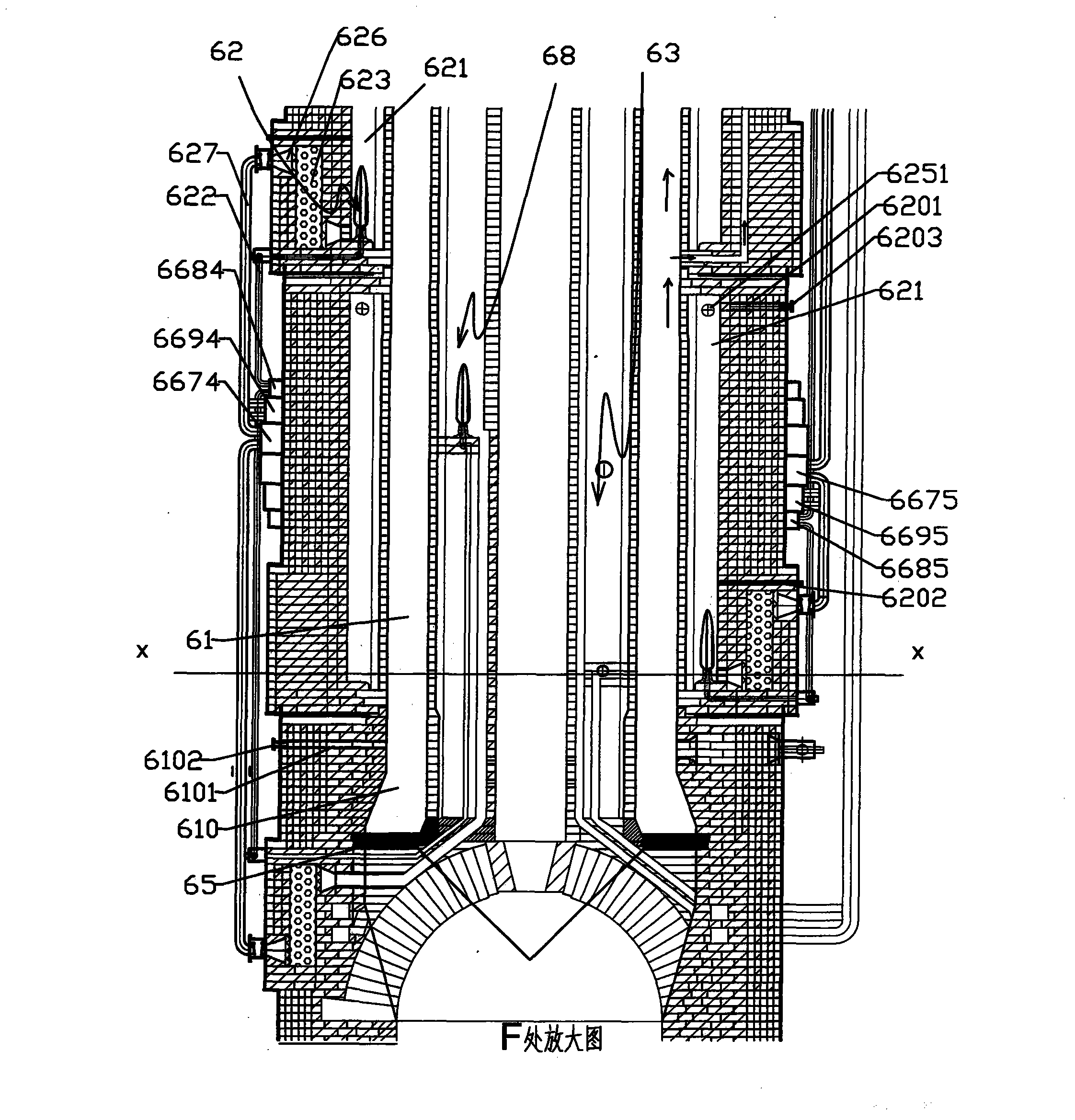
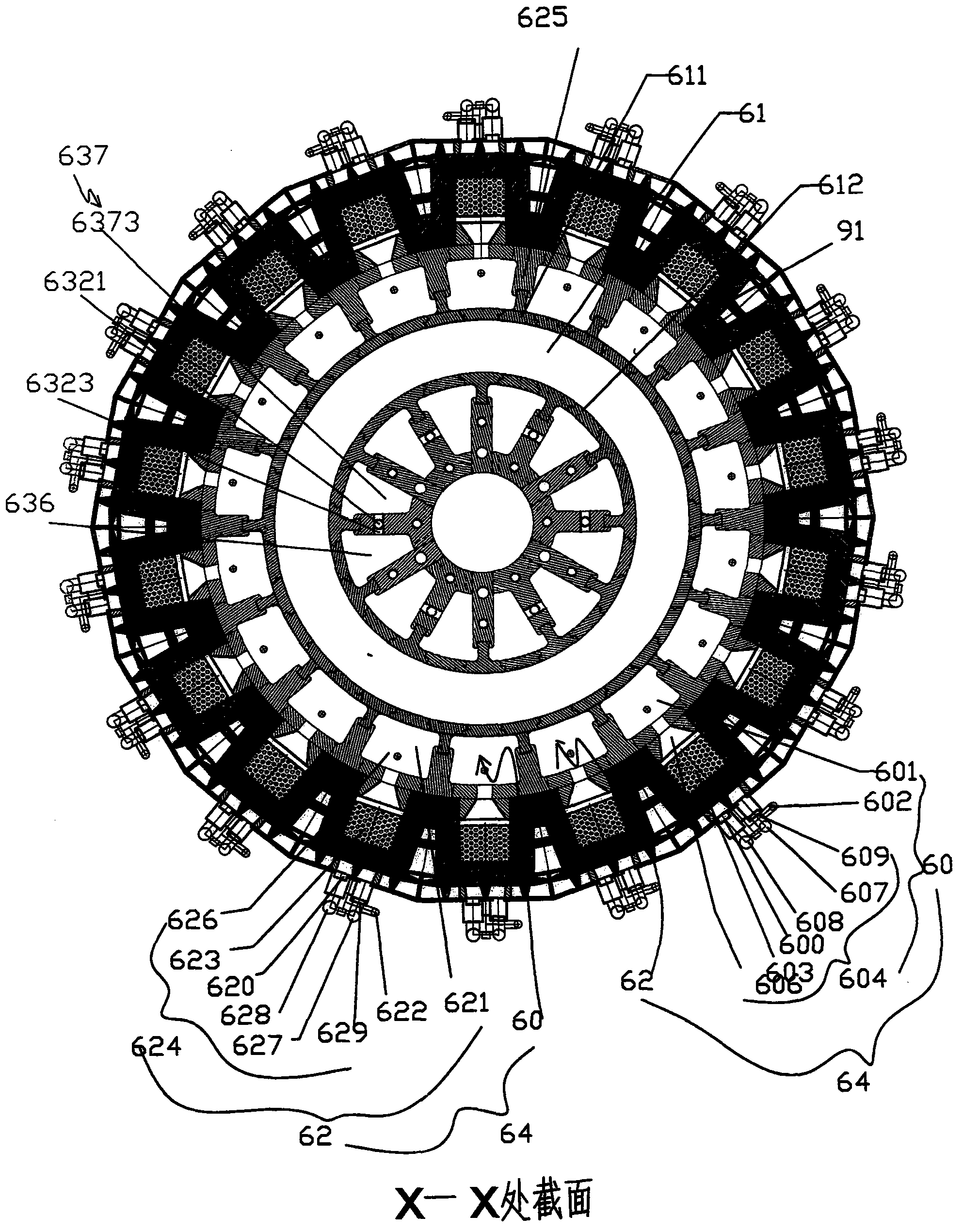
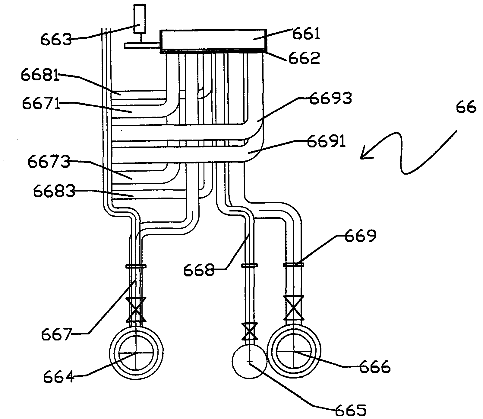
The invention discloses a quenching waste gas heater of a coal pyrolyzing furnace. The quenching waste gas heater mainly comprises an inner flame path, a primary air supplement pipe, a secondary air supplement pipe, a central ring wall and a central passage, wherein the inner flame path is separated into one or more than one group of main and secondary inner flame paths; the secondary inner flame path is divided into an upper section, a middle section and a lower section; a waste gas through hole is formed between the upper section of secondary inner flame path and the main inner flame path; a hot waste gas exhaust passage is arranged on the top part of the upper section of secondary inner flame path; a flame path through hole is formed between the lower section of secondary inner flame path and the main inner flame path; the central passage formed by the enclosure of the central ring wall is separated into an upper part of buffering area and a lower part of high-temperature combustible waste gas inlet passage; waste gas inlets are respectively formed between the buffering area and the main inner flame path, and between the buffering area and the upper section of secondary inner flame path; combustible waste gas inlets are formed between the high-temperature combustible waste gas inlet passage and the main inner flame path and between the high-temperature combustible waste gas inlet passage and the lower section of secondary inner flame path; the outlet of the primary air supplement pipe is respectively communicated to the main inner flame path and the lower section of secondary inner flame path; and the outlet of the secondary air supplement pipe is communicated to the main inner flame path. The high-temperature combustible waste gas generated by dry quenching is used for air supplement combustion heating, so that the quenching waste gas heater is environment-friendly and economical.

Description

technical field [0001] The invention relates to a waste gas combustion heater, in particular to a heater which burns combustible high-temperature waste gas generated by dry extinguishing of a coal pyrolysis furnace. Background technique [0002] At present, most coal pyrolysis furnaces (coke ovens) on the market adopt batch-type coking, and the process steps such as the proportion of coal into the furnace, dehydration, coal feeding, preheating, carbonization, coke reforming, and CDQ are relatively independent and cannot be carried out. Continuous production, low production efficiency; In addition, the raw coal gas produced in the coal pyrolysis process contains many useful components, such as H 2 S, HCH and other acid gases, NH 3 Alkaline gas, tar, benzene, naphthalene, washing oil and other organic substances do not have a complete process for exporting, recovering and purifying raw gas. [0003] This impels the inventors to explore and innovate a complete set of continuo...

Claims


Application Information

Patent Timeline
Patent Type & Authority Patents(China)
IPC IPC(8): C10B21/10C10B21/12
Inventor 王新民
Owner 山西睿得新材料科技有限公司
Why Eureka
Try Eureka