
Three-dimensional deformation measuring system and three-dimensional deformation measuring method combining speckle correlation and speckle interference

A technology of three-dimensional deformation and speckle interference, which is applied in measurement devices, instruments, and optical devices, etc., can solve the problems of complex image processing process, difficulty in obtaining three-dimensional deformation field values, and complex principles.

Inactive Publication Date: 2014-12-10
SHANDONG NORMAL UNIV
View PDF6 Cites 0 Cited by
  • Summary
  • Abstract
  • Description
  • Claims
  • Application Information

AI Technical Summary

Problems solved by technology

The principle used is very complicated, and the image processing process is also very complicated. When using speckle correlation to calculate the in-plane displacement, the required speckle image is not obtained directly, but is obtained by processing the phase-shifted images collected before and after deformation. In actual operation Difficult to obtain numerical values ​​for 3D deformation fields

Method used


Image

  • Three-dimensional deformation measuring system and three-dimensional deformation measuring method combining speckle correlation and speckle interference
  • Three-dimensional deformation measuring system and three-dimensional deformation measuring method combining speckle correlation and speckle interference
  • Three-dimensional deformation measuring system and three-dimensional deformation measuring method combining speckle correlation and speckle interference

Examples


Embodiment Construction

[0051] The present invention will be further described below in conjunction with the accompanying drawings and embodiments.

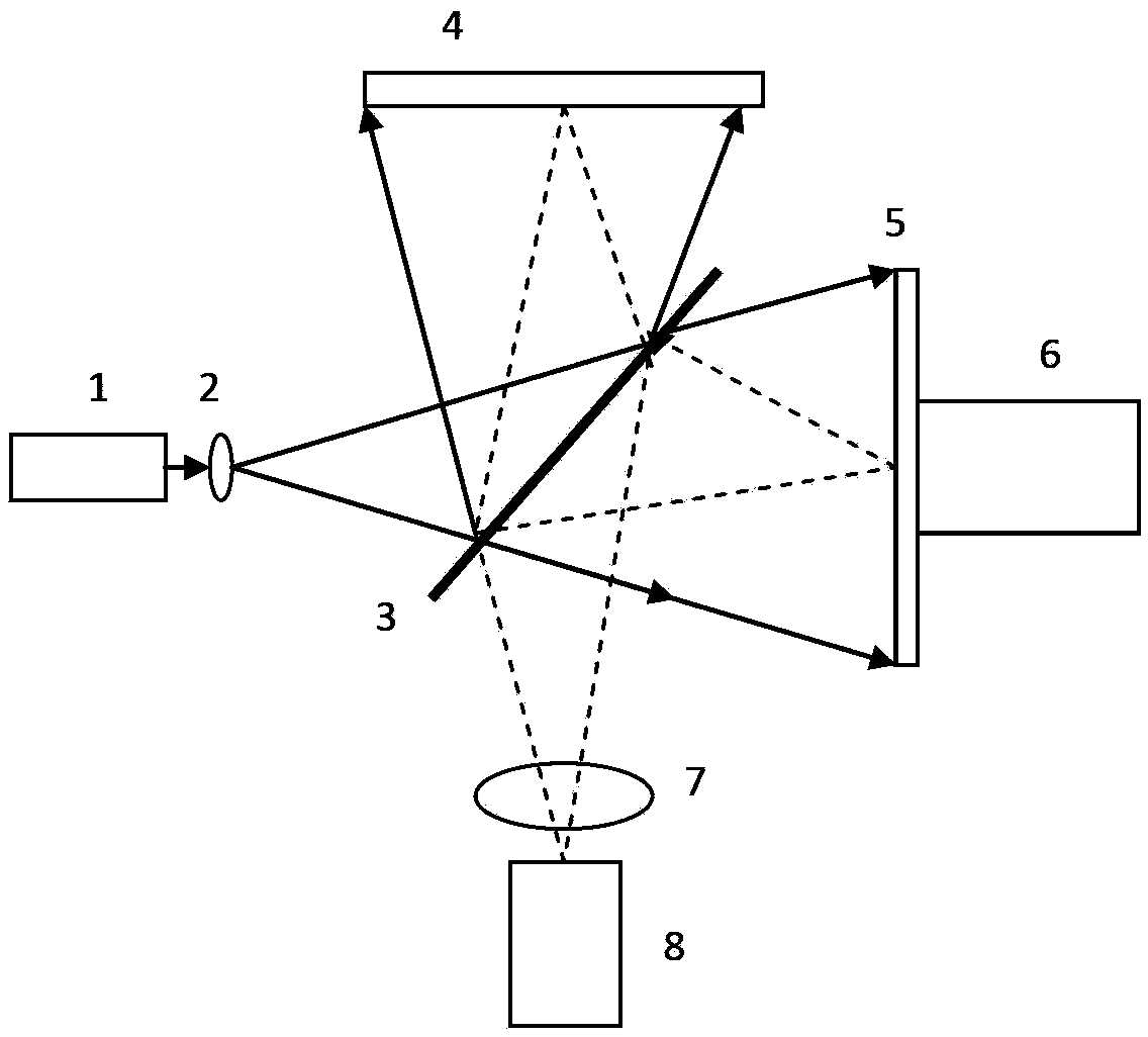
[0052] figure 1 , a three-dimensional deformation measurement system combining speckle correlation and speckle interference, which includes a speckle correlation optical path for measuring in-plane deformation components and a speckle interferometric phase-shift optical path for measuring out-of-plane displacement components; the laser 1 emits After the laser beam is expanded, the measured object surface 4 and the reference object surface 5 are respectively illuminated by the half mirror 3 . The half mirror 3 is placed obliquely at an angle of 45° to the incident light. The reflected light of the object plane 4 passes through the half-mirror 3 , the reflected light of the reference object plane 5 is reflected on the half-mirror 3 , and the two beams of light converge on the CCD camera 8 after passing through the imaging lens 7 .

[0053] Experimental ...


PUM


Abstract

The invention relates to a three-dimensional deformation measuring system and a three-dimensional deformation measuring method combining speckle correlation and speckle interference. The system comprises a laser, wherein laser light emitted by the laser passes through a semi-permeable and semi-reflective mirror after being expanded for illuminating a tested object and a reference object surface respectively; the tested object surface and the reference object surface are imaged simultaneously on the target surface of a CCD (Charge Coupled Device) camera through an imaging lens by means of the semi-permeable and semi-reflective mirror; the semi-permeable and semi-reflective mirror is arranged obliquely at an angle of 45 degrees relative to incident rays; and when a reference path exists, object surface speckles and reference surface speckles are interfered with mutually on the target surface of the CCD camera to form an interference speckle image for measuring an off-plane displacement component. A reference substance light path is removed, a speckle image on the object surface is acquired, and two components of in-plane displacement are calculated by using two speckle images acquired before and after deformation. A typical digital speckle light path which is sensitive to the off-plane displacement is utilized, so that the in-plane displacement and speckle interference off-plane displacement of a speckle relevance measuring object are realized, and three-dimensional displacement measurement is realized; and and the system and the method have the advantages of simple light path, and easiness and rapidness for operating and processing data.

Description

technical field [0001] The invention relates to a three-dimensional deformation measurement system and method, in particular to a three-dimensional deformation measurement system and method combining speckle correlation and speckle interference. Background technique [0002] The digital speckle image correlation method (Digital Speckle Correlation Method, DSCM) proposed by I Yamaguchi, W.H.Peters and W.F.Ranson et al. Many application fields such as dynamic displacement and deformation testing have demonstrated its applicability and superiority. Digital speckle image correlation technology records the images before and after deformation of the object and uses a certain image correlation search algorithm to obtain the displacement and deformation of the object. It has the advantages of simple principle, simple optical path, non-contact, and low requirements for the measurement environment. In recent years, some modern mathematical theories and methods have been gradually int...

Claims


Application Information

Patent Timeline
Patent Type & Authority Patents(China)
IPC IPC(8): G01B11/16G01B11/02
Inventor 孙平孙明勇
Owner SHANDONG NORMAL UNIV
Learn More