Piezoresistive micromechanical sensor component and corresponding measuring method

A technology of micro-mechanical sensor and measurement method, which is applied in the direction of measuring device, acceleration measurement, speed/acceleration/shock measurement, etc., can solve the problems of process consumption, etc., and achieve the effect of favorable cost, high mechanical sensitivity, and simplified technical realization

A technology of micro-mechanical sensor and measurement method, which is applied in the direction of measuring device, acceleration measurement, speed/acceleration/shock measurement, etc., can solve the problems of process consumption, etc., and achieve the effect of favorable cost, high mechanical sensitivity, and simplified technical realization

CN102792169AInactive Publication Date: 2012-11-21ROBERT BOSCH GMBH

Image

  • Piezoresistive micromechanical sensor component and corresponding measuring method
  • Piezoresistive micromechanical sensor component and corresponding measuring method
  • Piezoresistive micromechanical sensor component and corresponding measuring method

Examples


Embodiment Construction

[0025] In the figures, identical reference numbers designate identical or functionally identical components.

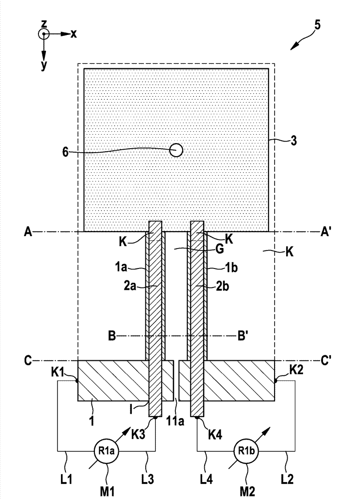
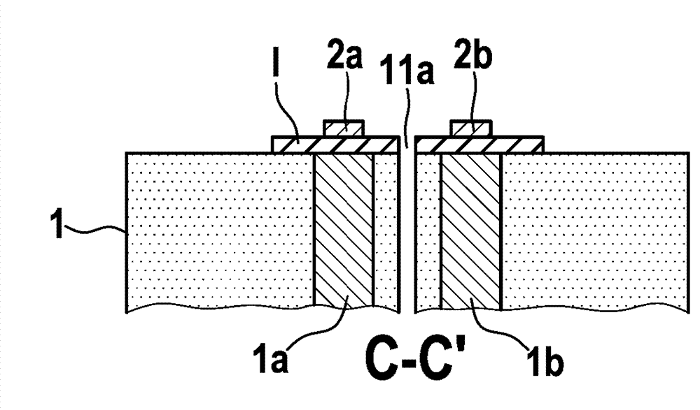
[0026] figure 1 is a top view of a piezoresistive micromechanical sensor device in the form of a micromechanical acceleration sensor device according to a first embodiment of the invention, and Figure 2a -c is based on figure 1 A cross-section along lines AA1', BB' and CC' of a piezoresistive micromechanical sensor device in the form of a micromachined acceleration sensor device.

[0027] exist figure 1 , reference numeral 5 shows a piezoresistive micromachined acceleration sensor. Starting from the substrate 1, two uniformly doped piezoresistive beams 1a, 1b extend to the anti-seismic mass 3, whereby the anti-seismic mass is connected to the substrate 1 via the beams 1a, 1b. There is a cavity K below the beams 1 a , 1 b and the seismic mass 3 .

[0028] The insulating trench G between the piezoresistive beams 1 a , 1 b can also be embodied as a narrow insula...


PUM


Abstract

The present invention relates to a piezoresistive micromechanical sensor component and to a corresponding measuring method. The piezoresistive micromechanical sensor component comprises: a substrate (1); a seismic mass (3) which is suspended from the substrate such that it can be deflected; at least one piezoresistive bar (1a, 1b; 1a', 1b') which is provided between the substrate and the seismic mass and is subject to a change in resistance when the seismic mass is deflected; wherein the piezoresistive bar has a lateral and / or upper and / or lower conductor track (2a, 2b; 2a', 2b') which at least partially covers the piezoresistive bar and extends into the region of the substrate; and a measuring device (M1; M2; M1'; M1'') which is electrically connected to the substrate and to the conductor track and is designed to measure the change in resistance over a circuit path which runs from the substrate through the piezoresistive bar and from the piezoresistive bar through the lateral and / or upper and / or lower conductor track.

Description

technical field [0001] The invention relates to a piezoresistive micromechanical sensor device and a corresponding measuring method. Background technique [0002] Although applicable to any piezoresistive micromechanical sensor device, the invention and the problem on which it is based are explained with reference to a piezoresistive micromechanical acceleration sensor. [0003] Current acceleration sensors are usually analyzed capacitively. But equally practical piezoresistive analysis offers greater potential in terms of the ever-wider miniaturization that is being pursued. In principle, in the case of piezoresistive acceleration sensors (referred to here as piezoresistive acceleration sensors), the following two variants are to be distinguished. [0004] A variant consists in structured doping, in which the piezoresistors are doped at those points on the crossbar at which the maximum mechanical stress occurs in the event of a deflection. [0005] Another variant consis...

Claims


Application Information

Patent Timeline
21 Nov 2012
Publication
CN102792169A
IPC
G01P15/08; G01P15/12; H10N30/30
CPC
G01P15/123; G01P15/0802; G01P15/08; G01P15/12; G01P15/09
Inventors
R.诺伊尔; C.雷蒂希