

Methods and apparatus for forming multi-layer structures using adhered masks
- Summary
- Abstract
- Description
- Claims
- Application Information
AI Technical Summary
Benefits of technology
Problems solved by technology
Method used
Image

Examples
first embodiment
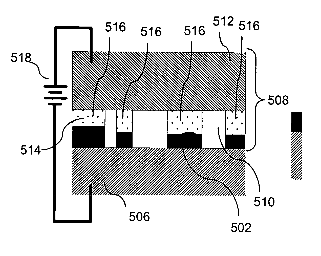
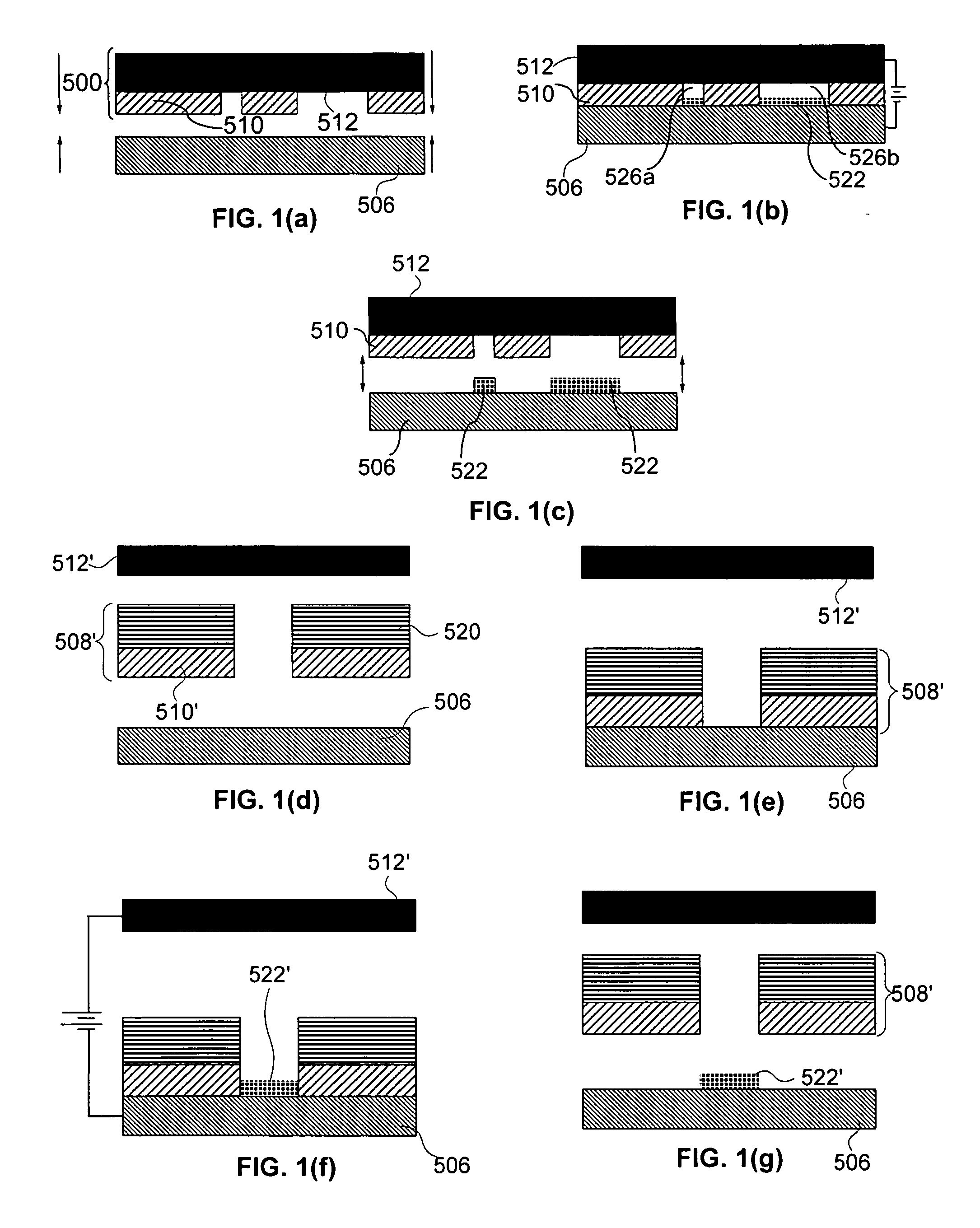
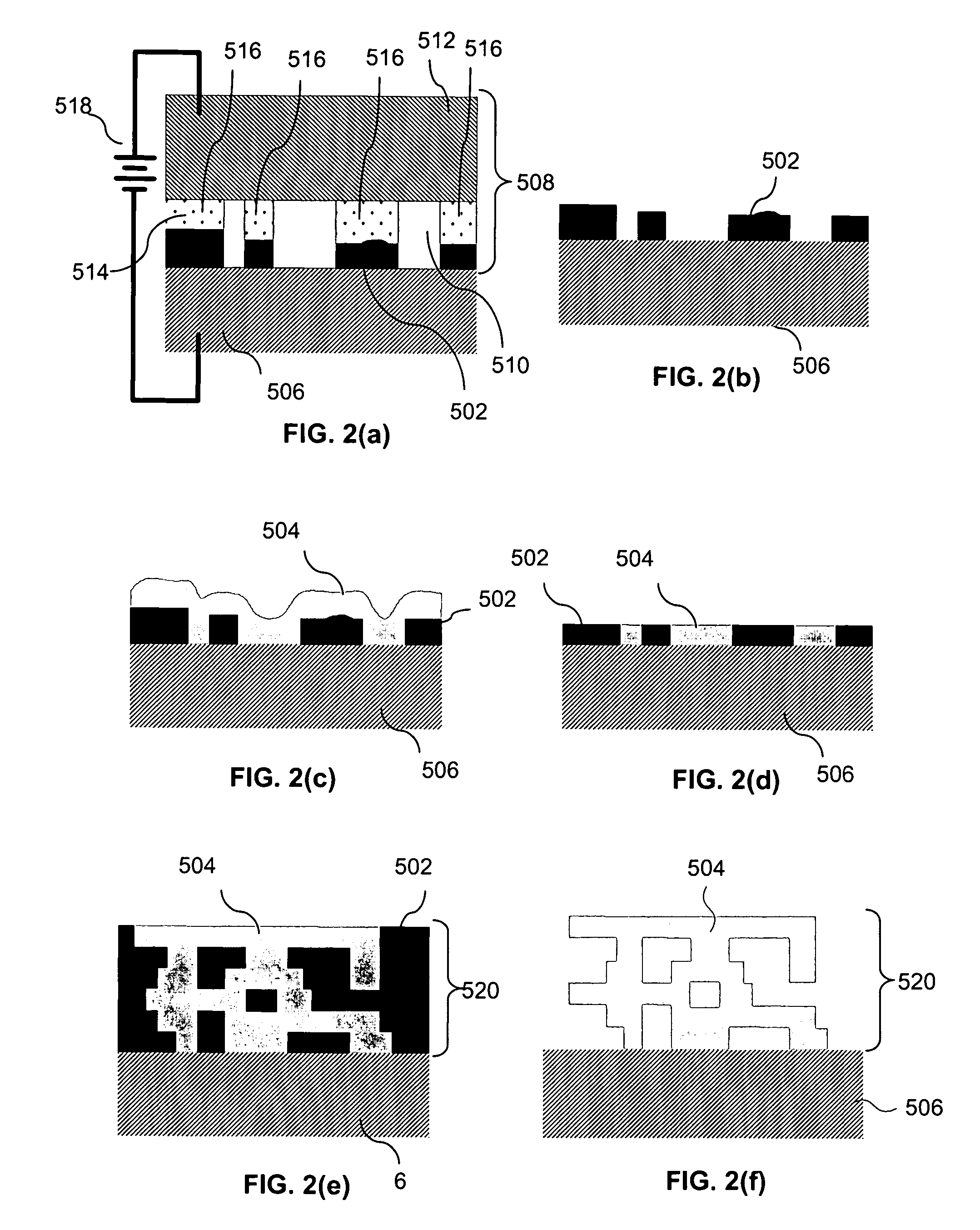
[0169] FIGS. 5(a)-(ii) illustrate schematic side views of the states of the process and apparatus components involved in forming a sample structure according to the invention. In this embodiment, a carrier is provided for carrying a substrate on which layers of material will be formed during fabrication of a structure.
[0170]FIG. 36(a)-(d), schematically depict side views of various relationships between a carrier and a substrate that may be used in some embodiments of the invention. FIG. 36(a) depicts a substrate without a carrier and thus indicates that in some embodiments of the invention, a substrate 192 may be used without a carrier. FIGS. 36(b)-36(c) depict some other relationships that may exist in other embodiments. In some embodiments a carrier 194 may have the same size as the substrate 192, as shown in FIG. 36(b). Other embodiments may use a carrier 196 that is larger than the substrate 192, as shown in FIG. 36(c). Still other embodiments, may be use or include a carrier 1...
second embodiment
[0226] Both embodiments allow for alignment of each successive photomask pattern to carrier 1 (i.e., to substrate 25) rather than to the previously-deposited layer, to advantageously avoid the accumulation of errors that can lead to poor registration of layers. In the first approach, imaging system 49 (here assumed to be an electronic camera with microscope optics, though direct observation is also possible with the second embodiment) can be moved vertically on precision stage 50, preferably having excellent straightness of travel with minimal roll, pitch, and yaw or translation other than axial. Stage 50 is preferably aligned so that its axis of travel is both extremely parallel to the optical axis of system 49, and extremely perpendicular to the photomask bottom surface (i.e., coating 39).
[0227] In the position shown, system 49 can focus on target 35 in its current position. As layers are added and carrier 1 descends gradually, system 49 can be lowered on stage 50 in order to rema...
PUM
| Property | Measurement | Unit |
|---|---|---|
| Angle | aaaaa | aaaaa |
| Thickness | aaaaa | aaaaa |
| Polarity | aaaaa | aaaaa |
Abstract
Description
Claims
Application Information