Biopsy Devices, Methods for Using, and Methods for Making

Inactive Publication Date: 2007-09-20
MICROFAB
15 Cites 66 Cited by

AI-Extracted Technical Summary

Problems solved by technology

The CC mask plating process is distinct from a “through-mask” plating process in that in a through-mas...

Method used

[0083]“Build layer” or “layer of structure” as used herein does not refer to a deposit of a specific material but instead refers to a region of a build located between a lower boundary level and an upper boundary level which generally defines a single cross-section of a structure being formed or structures which are being formed in parallel. Depending on the details of the actual process used to form the structure, build layers are generally formed on and adhered to previously formed build layers. In some processes the boundaries between build layers are defined by planarization operations which result in successive build layers being formed on substantially planar upper surfaces of previously formed build layers. In some embodiments, the substantially planar upper surface of the preceding build layer may be textured to improve adhesion between the layers. In other build processes, openings may exist in or be formed in the upper surface of a previous but only partially formed build layers such that the openings in the previous build layers are filled with materials deposited in association with current build layers which will cause interlacing of build layers and material deposits. Such interlacing is described in U.S. patent application Ser. No. 10/434,519. This referenced application is incorporated herein by reference as if set forth in full. In most embodiments, a build layer includes at least one primary structural material and at least one primary sacrificial material. However, in some embodiments, two or more primary structural materials may used without a primary sacrificial material (e.g. when one primary structural material is a dielectric and the other is a conductive material). In some embodiments, build layers are distinguishable from each other by the source of the data that is used to yield patterns of the deposits, applications, and/or etchings of material that form the respective build layers. For example, data descriptive of a structure to be formed which is derived from data extracted from different vertical levels of a data representation of the structure define different build layers of the structure. The vertical separation of successive pairs of such descriptive data may define the thickness of build layers associated with the data. As used herein, at times, “build layer” may be loosely referred simply as “layer”. In many embodiments, deposition thickness of primary structural or sacrificial materials (i.e. the thickness of any particular material after it is deposited) is generally greater than the layer thickness and a net deposit thickness is set via one or more planarization processes which may include, for example, mechanical abrasion (e.g. lapping, fly cutting, polishing, and the like) and/or chemical etching (e.g. using selective or non-selective etchants). The lower boundary and upper boundary for a build layer may be set and defined in different ways. From a design point of view they may be set based on a desired vertical resolution of the structure (which may vary with height). From a data manipulation point of view, the vertical layer boundaries may be defined as the vertical levels at which data descriptive of the structure is processed or the layer thickness may be defined as the height separating successive levels of cross-sectional data that dictate how the structure will be formed. From a fabrication point of view, depending on the exact fabrication process used, the upper and lower layer boundaries may be defined in a variety of different ways. For example by planarization levels or effective planarization levels (e.g. lapping levels, fly cutting levels, chemical mechanical polishing levels, mechanical polishing levels, vertical positions of structural and/or sacrificial materials after relatively uniform etch back following a mechanical or chemical mechanical planarization process). For example, by levels at which process steps or operations are repeated. At levels at which, at least theoretically, lateral extends of structural material can be changed to define new cross-sectional features of a structure.
[0108] Prior devices for such removal purposes are described, for example, in the paper “Barbed micro-spikes for micro-scale biopsy” (Byun et. Al, J. Micromech. Microeng. 15 (2005) 1279-1284). This referenced paper is incorporated herein by reference. In this paper, a barbed biopsy device is fabricated from silicon. It is pushed into the tissue to be biopsied and then withdrawn, such that barbs formed on the sides of protruding sections of the device retain tissue. It is noted by the authors that the ability of such devices to excise tissue is greatly enhanced by the addition of the barbs. The device described in this paper has significant disadvantages and limitations. These limitations include: [0109] Silicon is a brittle material, so the risk of device breakage and harm to the patient is significant. [0110] Since there is no ‘floor’ and ‘ceiling’ surrounding the barbs to retain the specimen, it can easily slip away from the barbs and be lost. Loss of the specimen may in some cases (e.g., the cardiovascular system) present a significant risk to the patient. Moreover, the lack of a floor and ceiling makes the sample that can be obtained typically smaller, and the ability to obtain it less reliable, since tissue can ‘escape capture’ through the open top and bottom.
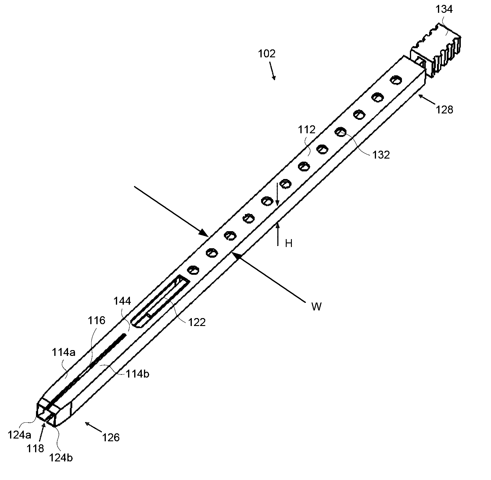
[0112]FIG. 5 provides a perspective overview of the device of a first preferred embodiment. The device 102 includes a body portion 112 terminating at the distal end 126 in two jaws 114a and 114b that are initially substantially parallel, separated by a slot 116. The distal ends of the jaws 114a and 114b are preferably made sharp to serve as cutting edges 124a and 124b and are separated by an inlet 118. An aperture 122 is provided in the body 112 of the device to provide clearance for squeezing the device, as will be discussed below. In some alternative embodiments, such an aperture may not be necessary. The aperture 122 also serves, as do a plurality of release holes 132, to allow sacrificial material to be etched out (e.g. after fabrication of all layers of the device) when the device is fabricated using an electrochemical fabrication process that involves the use of a sacrificial material to fill portions of each layer that are not occupied by a structural material that defines part of the device. Also shown in the figure is a handle 134, at the proximal end 128 of the body 112, which controls whether the jaws remain closed for sampling or whether they are opened for specimen removal. The body preferably as a width, W, and a height, H, are selected to produce samples of a desired size while minimizing damage to tissue that must be penetrated to get to the extraction site. The width and height may also be selected to allow the device to fit through a lumen in a catheter or other delivery device if it is to be passed to the extraction site via such a passage.
[0114]FIG. 8A and 8B illustrate schematically a closed and open state of the jaws of the device of FIG. 5. In FIG. 8A the jaws 114a and 114b are in a substantially parallel configuration (i.e. not opened). This is the state of the jaws when the device 102 is inserted into tissue to obtain a specimen. In FIG. 8B, the jaws 114a and 114b have been forced into an open configuration which allows easy removal of the organ or tissue specimen. This open, V-shaped, or spread configuration results from squeezing the device in the region of the aperture 122 which results in the deforming of the body of the device (elastically or plastically) and the spreading open of the jaws 114a and 114b about fulcrum which results in the deforming of the body of the device (elastically or plastically). In some alternative embodiments, the fulcrum may take on other configurations so as to enhance the ability of the jaws to open. For example, the fulcrum may be physically bonded, adhered, or connected to only one jaw or the other so that upon squeezing the aperture, one jaw tends to undergo a larger angular displacement than the other. In still other alternatives the fulcrum may take on a sharper or more pointed configuration where it contacts or both jaws. In still other embodiments, the fulcrum may be replaced by a pin and rings connected separately to one or both jaws to allow pivoting or rotation from a closed to an open state.
[0115] In this first embodiment, the device is provided with a mechanism to prevent premature spreading of the jaws that may result from improper handling, tissue reaction forces, and the like. In alternative embodiments, such a mechanism may not be necessary. An example of such a mechanism or retainer 152 is visible in the cross-sectional top view of the device as shown in FIG. 9. The handle 134 is attached to a retainer shaft 154 that passes through an opening 156 that extends along the length of the body 112 of the device 102. At the distal end of this shaft a retainer 152 is located which preferably has a tapered shape such that when the shaft is moved toward the distal end of the body, the distal end of the retainer 152 can engage bosses 158a and 158b on the jaws to prevent the jaws from spreading open. The bosses may be located at the proximal end of the jaws or they may, as in the present case, be located between the distal and proximal ends of the jaws. In some alternative devices, the retainer may be located in the region of the aperture and simply prevent collapse of the aperture and thus prevent the spreading of the jaws. In some alternative embodiments, as noted above, a mechanism to inhibit spreading may not be required.
[0116] In some embodiments, as in the present embodiment, the barbs on the jaws may have outward facing sloped surfaces that allow easy slide in entry of tissue while their back surfaces may be substantially perpendicular to the slide-in direction. In still other embodiments the slope of the back ends of the barbs may not be perpendicular to the slide-in direction but may be more steeply sloped than the outward facing surfaces. In still other embodiments, the back ends of the barbs may be undercut (i.e. oblique relative to the slide-in direction) to provide a positive retention forces (i.e. a true barb) that inhibits tissue from being released from the distal end of the device.
[0120] The device of FIG. 5 may be operated according to the following sequence of operations: [0121] 1. The handle is moved distally relative to the body 112 of the device 102 so that the retainer engages the bosses on the jaws. [0122] 2. While the handle is held in this distal position, relative to the body of the device, the device is pushed into the tissue (e.g., by pushing distally on the handle or distally along the body of the device) to be sampled, causing a specimen of tissue to enter the device inlet while its edges are being cut by edges 124a and 124b. Since the jaws are prevented from spreading by the retainer engaging the bosses, the specimen is slightly compressed within the inlet of the device. [0123] 3. The device 102 and sample are then withdrawn from the tissue. Since the specimen within the barbed jaws is largely unable to be removed from the distal ends of the jaws, the specimen becomes separated adja...

Benefits of technology

[0039] A need exists in various fields for miniature devices having improved characteristics, reduced fabrication times, reduced fabrication costs, simplified fabrication processes, greater versatility in device design, ...

Abstract

Embodiments of invention are directed to devices, and methods of forming them, that can be used for removal of small volumes of tissue from the body, as is required for biopsy procedures. The procedures may be of the image-guided or non image-guided type. The devices described herein are applicable to biopsy of many types of tissue, particularly soft tissue. Applications include biopsy of the intestines, stomach, breast, pancreas, lung, liver, brain, skin, prostate, thyroid, heart, and other organs and tissues. Embodiments are directed to devices formed from a plurality of adhered layers of deposited materials.

Application Domain

SurgeryVaccination/ovulation diagnostics

Technology Topic

Pancreatic structureProstate +8

Image

  • Biopsy Devices, Methods for Using, and Methods for Making
  • Biopsy Devices, Methods for Using, and Methods for Making
  • Biopsy Devices, Methods for Using, and Methods for Making

Examples

  • Experimental program(7)

Example

[0053]FIG. 5 provides a perspective overview of the device of the first embodiment.
[0054]FIGS. 6-7 provide alternative, perspective views of the distal end of the device of FIG. 5
[0055]FIG. 8A and 8B illustrate schematically a closed and open state of the jaws of the device of FIG. 5.
[0056]FIG. 9 provides a cross-sectional view through the device of FIG. 5 along the plane including the height and length of the device.
[0057]FIGS. 10-11 provide respectively a plan view of the distal end of the device of FIG. 5 holding a specimen and a perspective view of the distal end of the device.
[0058]FIG. 12 provides a cross-sectional view of the device of FIG. 5 in the region of the fulcrum.
[0059]FIGS. 13A-13I illustrate an alternative to an EFAB™ process for producing a device like that of FIGS. 5-FIG. 12.

Example

[0060]FIGS. 14 and 15 provide perspective view from distal and proximal ends, respectively, of a device according a second embodiment of the invention.
[0061]FIG. 16 provides a close up perspective view of the jaws of the device of FIGS. 14 and 15.
[0062]FIGS. 17 and 18 provide, respectively, perspective and plan cross-sectional views of the device of FIGS. 14-16 showing the internal springs and other details.
[0063]FIGS. 19 and 20 provide cross-sectional perspective views of the distal end of the device of FIGS. 14-18 taken at different cross-sectional levels with different perspectives.
[0064]FIGS. 21 and 22 provide perspective views of the distal end of the device of FIGS. 14-20 taken from different perspectives.
[0065]FIGS. 23A-23F provide a schematic representation of various stages of operation of a third embodiment of the invention.
[0066] In FIG. 24 provides a perspective view of an example device of that is capable of being operated according to the method of use set forth in FIGS. 23A-23F.
[0067]FIGS. 25-30 show additional views of the device of FIG. 24 some of which are plan views, some of which are perspective views and some of which show hidden lines keeping elements that cannot be directly seen.
[0068]FIGS. 31 and 32 provide cross-sectional views through the device of FIGS. 24-30 along a plane that is perpendicular to a preferred build axis while FIG. 33 provides a cross-sectional view through the device of FIGS. 24-32 along a plane that includes the build axis and the longitudinal axis of the device.
[0069]FIG. 34 shows a cross-sectional view of the distal end of the device of FIGS. 24-33 as cut through the barrel pivots.

Example

[0070]FIG. 35 shows a partial view of a distal end of a device according to a fourth embodiment of the invention.

PUM

no PUM

Description & Claims & Application Information

We can also present the details of the Description, Claims and Application information to help users get a comprehensive understanding of the technical details of the patent, such as background art, summary of invention, brief description of drawings, description of embodiments, and other original content. On the other hand, users can also determine the specific scope of protection of the technology through the list of claims; as well as understand the changes in the life cycle of the technology with the presentation of the patent timeline. Login to view more.

Similar technology patents

Full color organic light-emitting device having color modulation layer

ActiveUS20050062407A1reduce fabrication timehigh resolution
Owner:SAMSUNG DISPLAY CO LTD

Methods and apparatus for forming multi-layer structures using adhered masks

InactiveUS20050023145A1improved structural propertyreduce fabrication time
Owner:MICROFAB

Tropoelastins and uses thereof

ActiveUS20130164340A1improve characteristiclow quality
Owner:PROTEIN GENOMICS

Temperature sensing oscillator circuit

InactiveUS20050141589A1improve characteristic
Owner:SK HYNIX INC

Gas diffusion layer and fuel cell using the same

ActiveUS20050214630A1decrease in cell outputimprove characteristic
Owner:PANASONIC CORP

Classification and recommendation of technical efficacy words

  • improve characteristic
  • reduce fabrication time

Atomic Layer Deposition Apparatus and Process

ActiveUS20120269968A1improve characteristicfacilitate growth
Owner:KURT J LESKER

Absorbent pad

InactiveUS20070219523A1improve characteristiceasy and inexpensive to manufacture
Owner:ATTENDS HEALTHCARE

Contact structure for nanometer characteristic dimensions

InactiveUS20050200026A1improve characteristic
Owner:TAIWAN SEMICON MFG CO LTD

Methods and apparatus for forming multi-layer structures using adhered masks

InactiveUS20050023145A1improved structural propertyreduce fabrication time
Owner:MICROFAB

Full color organic light-emitting device having color modulation layer

ActiveUS20050062407A1reduce fabrication timehigh resolution
Owner:SAMSUNG DISPLAY CO LTD
Why Eureka
Try Eureka