Radiation detector and method for manufacturing same

a technology of radiation detector and manufacturing method, which is applied in the field of radiation detector, can solve the problems of high fabrication cost, conventional radiation detector, and difficult to implement a large area, and achieve the effect of reducing fabrication cost and fabrication time, and small thickness

Active Publication Date: 2018-07-12
KOREA ATOMIC ENERGY RES INST
View PDF0 Cites 5 Cited by
  • Summary
  • Abstract
  • Description
  • Claims
  • Application Information

AI Technical Summary

Benefits of technology

[0021]In the present invention, the scintillator may be formed of a two-dimensional nanomaterial including a graphene oxide, a reduced graphene oxide, and graphene quantum dots, and the light detector may be formed by using a two-dimensional nanomaterial including graphene.
[0022]Accordingly, the radiation detector may have flexibility and a small thickness due to a characteristic of its material.
[0023]Further, in the present invention, the radiation detector of a large area may be manufactured through a printing process, without using expensive semiconductor equipment through a process of directly forming a light detector on a surface of a scintillator. This may reduce a fabrication cost and a fabrication time.

Problems solved by technology

However, the scintillator has disadvantages that the compounds are voluminous and stable, and it is difficult to implement a large area.
Further, it takes a lot of time to grow a single crystal when manufacturing the radiation detector, and growing conditions are complicated, resulting in high fabrication costs.
The conventional radiation detector where a scintillator and a light detector are coupled to each other is not flexible, and has a difficulty in operation in a bent or folded state.
As a result, it is difficult to apply the conventional radiation detector to a wearable or foldable device.
Further, it is difficult to apply the radiation detector to a large place for a missile search or a container search using radiation.
Further, there is a disadvantage that the radiation detector has its thickness increased after being manufactured.

Method used


Image

  • Radiation detector and method for manufacturing same
  • Radiation detector and method for manufacturing same
  • Radiation detector and method for manufacturing same

Examples


Embodiment Construction

[0041]Hereinafter, embodiments of the present invention will be explained in more detail with reference to the attached drawings.

[0042]For the sake of brief description with reference to the drawings, the same or equivalent components will be provided with the same reference numbers, and description thereof will not be repeated. A singular expression in the specification includes a plural meaning unless it is contextually definitely represented.

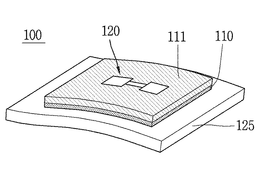
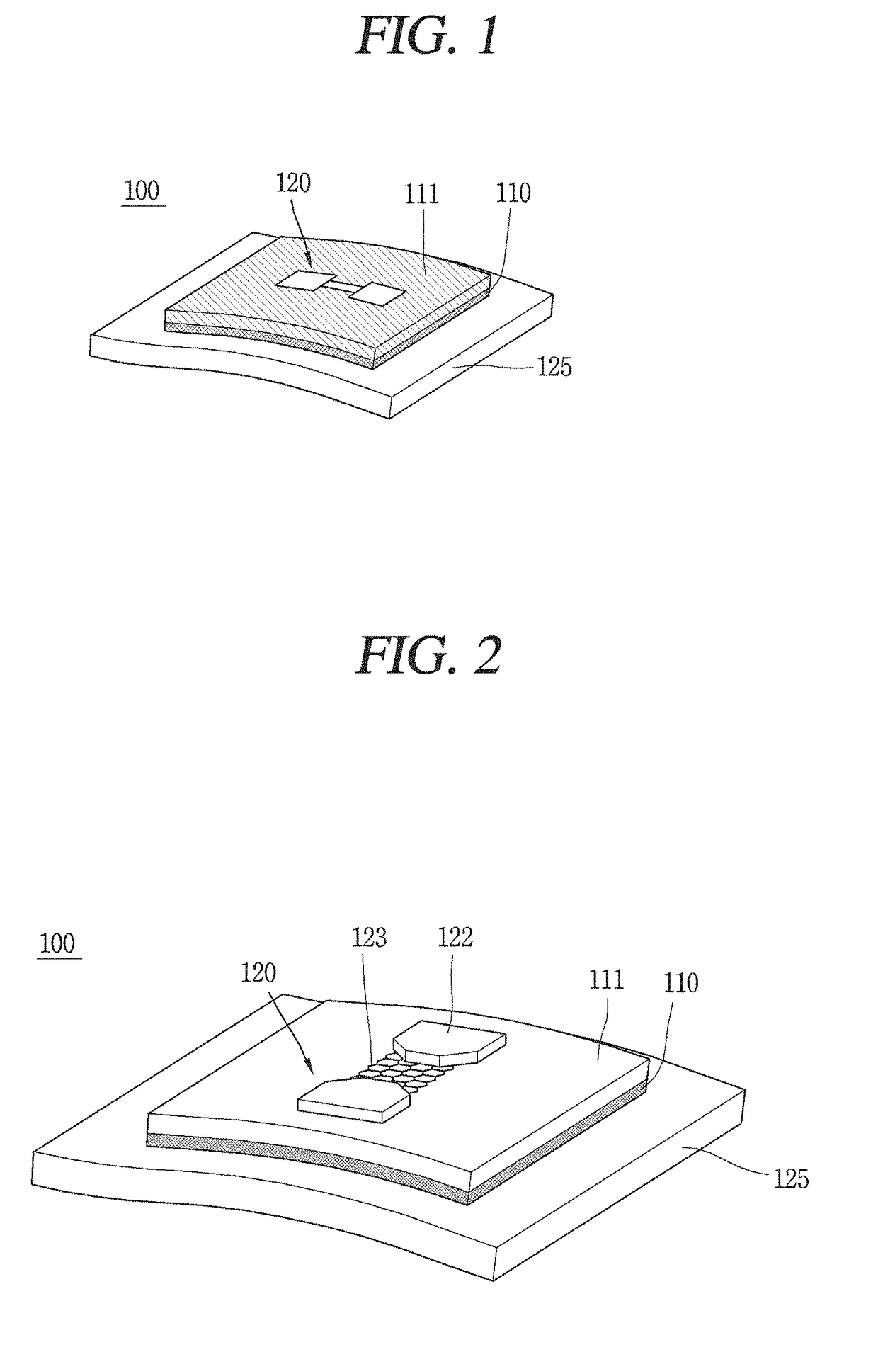
[0043]FIGS. 1 and 2 show a structure of a radiation detector 100 according to the present invention. FIG. 1 is a conceptual view showing that a radiation detector of the present invention is coupled to a substrate 125, and FIG. 2 is a perspective view showing a structure of the radiation detector.

[0044]The substrate 125 generally means a silicon oxide substrate formed of SiO2, but may be a substrate having a flexible property or various types of substrates on which the radiation detector 100 is to be positioned. Alternatively, the substrate 1...


PUM


Abstract

The present invention provides a radiation detector comprising: a scintillator for absorbing radiation to generate light; and a light detector formed in the scintillator, wherein the scintillator is composed of a two-dimensional nanomaterial for imparting ductility. The scintillator is formed by laminating the two-dimensional nanomaterial, the two-dimensional nanomaterial being at least one of graphene oxide, reduced graphene oxide, and graphene quantum dots.

Description

TECHNICAL FIELD[0001]The present invention relates to a radiation detector and a method for manufacturing the same.BACKGROUND ART[0002]A radiation detector for measuring radiation has various types, and a scintillator type radiation detector has a structure that a scintillator for generating light when radiation is incident thereon is coupled to a light detector for detecting the generated light.[0003]The scintillator is based on comparatively expensive crystalline compounds such as LaBr3, LYSO, Gd2SiO5(GSO), Bi4Ge3O12(BGO), NaI, CsI, TlBr and HgI2. However, the scintillator has disadvantages that the compounds are voluminous and stable, and it is difficult to implement a large area. Further, it takes a lot of time to grow a single crystal when manufacturing the radiation detector, and growing conditions are complicated, resulting in high fabrication costs.[0004]Generally, a light detector is manufactured based on a semiconductor wafer having a great thickness and a hard characteris...

Claims


Application Information

Patent Timeline
Patent Type & Authority Applications(United States)
IPC IPC(8): G01T1/20G01T1/202
CPCG01T1/2006G01T1/2023G01T1/2002G01T1/20
Inventor KANG, CHANGGOOHA, JANGHOOH, JOONHOKIM, HANSOOKIM, YOUNGSOOJEONG, MANHEE
Owner KOREA ATOMIC ENERGY RES INST
Why Eureka
Try Eureka