Flap wheel production device and production method

A technology for producing a device and a louver, which is applied to grinding devices, metal processing equipment, grinding/polishing equipment, etc., can solve the problems of increasing the production cost of the louver, unstable position of the glue applicator, and uneven coating of the chassis.

Inactive Publication Date: 2012-11-28
上海青浦良明工贸有限公司
View PDF6 Cites 12 Cited by
  • Summary
  • Abstract
  • Description
  • Claims
  • Application Information

AI Technical Summary

Problems solved by technology

[0003] Since the production of the louvers is mostly done manually, when the glue is applied to the chassis, it is easy to cause uneven application of the glue on the chassis, resulting in a reduction in the quality of the subsequent short blanks; at the same time, the production process of the short blanks is all done by Manually cutting long pieces piece by piece makes it difficult to guarantee product quality
It can be seen from the above that manual production leads to low production efficiency of the louver, and it is difficult to guarantee the quality of the product, and it also greatly increases the production cost of the louver
[0004] There are also chassis automatic gluing equipment in the prior art. However, the adjustment of the horizontal and vertical positions of many equipment is realized by connecting a shaft and a bushing to slide back and forth when gluing, so that the gluing head slides left and right, up and down. During the process, the force on the shaft is not uniform, and the position of the glue applicator is unstable, so that the glue on the chassis is not evenly applied

Method used


Image

  • Flap wheel production device and production method
  • Flap wheel production device and production method
  • Flap wheel production device and production method

Examples


Embodiment Construction

[0033] The invention discloses a production device of the louver, which improves the production efficiency of the louver; the invention also provides a production method of the louver.

[0034] The technical solutions in the embodiments of the present invention will be clearly and completely described below in conjunction with the accompanying drawings in the embodiments of the present invention. Obviously, the described embodiments are only some, not all, embodiments of the present invention. Based on the embodiments of the present invention, all other embodiments obtained by persons of ordinary skill in the art without making creative efforts fall within the protection scope of the present invention.

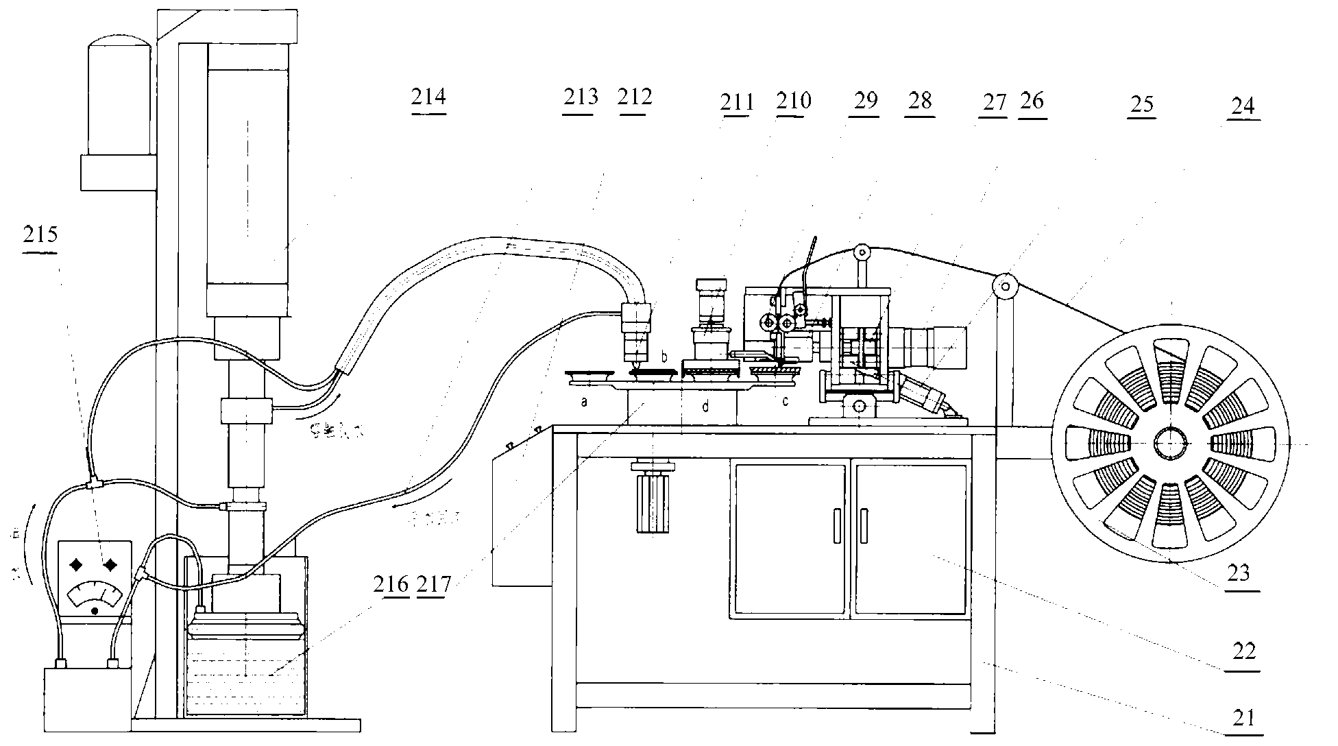
[0035] Such as figure 2 as shown, figure 2 Schematic diagram of the structure of the louver wheel production device provided by the present invention.

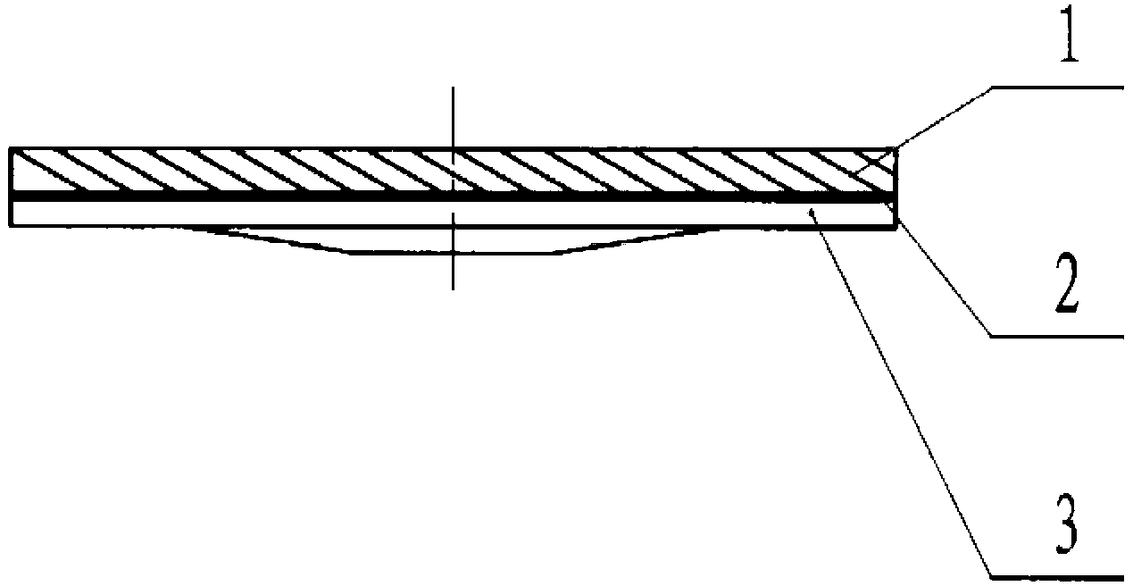
[0036] The invention provides a louver wheel production device. The material belt 4 is cut by a material belt cutting me...


PUM


Abstract

The invention provides a flap wheel production device which is used for cutting strips through a strip cutting mechanism. The strip cutting mechanism comprises a first compression roller and a second compression roller which are parallelly arranged, and the first and second compression rollers are in roll-in fit so as to convey strips, namely that a strip passing through a space between the two compression rollers is conveyed by using a drawing force generated by the mutual extrusion of the two compression rollers in the process of reverse rotation; and the conveyed strip is conveyed to a movable tool head, and then the strip is cut through the shearing fit of a main tool and an accessory tool. Through controlling the conveying speed of the first compression roller and the second compression roller and cooperating with the cutting interval of the movable tool head, strips in different sizes can be cut; the manual cutting of strips is converted into the automatic cutting of a strip cutting device, so that the cutting time of strips is reduced; and the strip subjected to cutting is conveyed to a swing mechanism for gluing and rotated on a chassis of a flap wheel so as to carry out circumferential arrangement and shaping on the strips subjected to cutting, thereby improving the production efficiency of flap wheels. The invention also provides a method for producing flap wheels.

Description

technical field [0001] The invention relates to the technical field of louver manufacturing, and more specifically, to a production device and method for a louver. Background technique [0002] The production of existing louvers is mainly done manually, such as figure 1 as shown, figure 1 Schematic diagram of the structure of the impeller. During production, glue is first manually applied on the chassis 3, and then the manually cut short piece 1 is pasted on the chassis 3, and the short piece 3 and the chassis 3 of the louver are bonded through the applied glue 2 , and finally the workers will reshape the chassis pasted with the short material, so that the louver reaches the specified shape of the louver. [0003] Since the production of the louvers is mostly done manually, when the glue is applied to the chassis, it is easy to cause uneven application of the glue on the chassis, resulting in a reduction in the quality of the subsequent short blanks; at the same time, the...

Claims


Application Information

Patent Timeline
Patent Type & Authority Applications(China)
IPC IPC(8): B24D18/00
Inventor 钱良
Owner 上海青浦良明工贸有限公司
Why Eureka
Try Eureka