Mechanical push-pull flexible shaft

A push-pull flexible shaft and mechanical technology, applied in the direction of flexible shafts, mechanical equipment, shafts, etc., can solve the problems of reducing the rigidity of the cable core, breaking the shaft core, reducing the bearing capacity of the cable core, etc., to reduce the contact area and small frictional resistance , The effect of reducing product cost

Inactive Publication Date: 2012-11-28
黄永炜
View PDF9 Cites 2 Cited by
  • Summary
  • Abstract
  • Description
  • Claims
  • Application Information

AI Technical Summary

Problems solved by technology

This design can improve the load efficiency and stroke efficiency of the push-pull flexible shaft, but due to the reason of the plastic coating layer, the rigidity of the cable core is reduced, thereby reducing the bearing capacity of the cable core, especially when the stroke in the thrust direction is large, After the cable core is pushed out of the protective tube, the section to the connection of the push-pull rod is suspended, and the reciprocating push-pull force makes the cable core continuously bend and deform, and the bending force and shear force accumulate at the connection part with the push-pull rod, resulting in the fracture of the shaft core

Method used


Image

  • Mechanical push-pull flexible shaft
  • Mechanical push-pull flexible shaft

Examples


Embodiment 1

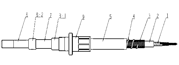
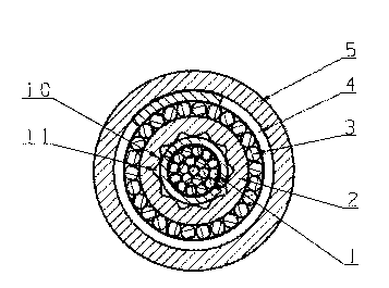
[0028] A mechanical push-pull flexible shaft, the flexible shaft has a smooth flexible shaft core 1, the surface of the flexible shaft core 1 is wrapped with a layer of conduit 2, and several arc-shaped ribs 10 are arranged around the inner hole of the conduit 2, and the outer surface of the conduit 2 is The surface is provided with a straight wire tube 3, the outer surface of the straight wire tube 3 has a layer of spiral belt protective layer 4, the outer surface of the spiral belt protective layer 4 is wrapped with a plastic layer 5, and the two ends of the mechanical push-pull flexible shaft are installed with pipe joints 9. Guide sleeve 7, push-pull rod 6, first seal 8-1 and second seal 8-2.

[0029] The flexible shaft core 1 is composed of a plurality of multi-layer parallel-strand steel wire ropes wrapped and pressed by two flat steel belts to make it solid overall, with a straight and smooth surface, good elasticity, rigidity and flexibility.

[0030] Several arc-shape...


PUM


Abstract

The invention relates to a mechanical push-pull flexible shaft, wherein the flexible shaft is provided with a flexible shaft core with a smooth surface; the surface of the flexible shaft core is wrapped by a layer of conduit; a plurality of arc-shaped ribs are distributed on the periphery of an inner hole of the conduit; a straight wire tube is arranged on the outer surface of the conduit; a spiral band protecting layer is arranged on the outer surface of the straight wire tube; the outer surface of the spiral band protecting layer is wrapped by a plastic layer; and a pipe joint, a guide sleeve, a push-pull rod and a sealing element are installed on two ends of the mechanical push-pull flexible shaft. With adoption of the mechanical push-pull flexible shaft provided by the invention, the contact area between the flexible shaft core and the inner surface of the conduit can be greatly reduced, the storage space of a lubricant can be increased and the lubrication conditions are improved to ensure that the friction resistance is smaller so as to obtain a higher load efficiency; the elastic deformation of a stress support point of the conduit is improved, and the fit clearance between the conduit and the flexible shaft core is guaranteed to be smaller so as to obtain a higher stroke efficiency; and because the rigidity of the flexible shaft core is stronger, the bearing capacity of the flexible shaft core is improved and the service life of the flexible shaft core is prolonged; and meanwhile, manufacturing processes are reduced and product cost is lowered.

Description

technical field [0001] The invention relates to automobiles, engineering machinery, agricultural and forestry machinery, and ship machinery, in particular to a mechanical push-pull flexible shaft. Background technique [0002] The mechanical push-pull flexible shaft is mainly used to transmit force and displacement. More specifically, it can bend or 360 degrees around obstacles to transmit pull and thrust. It is widely used in variable speed control systems of automobiles, construction machinery, agricultural and forestry machinery and ship machinery. . In the prior art, the contact area between the shaft core of the push-pull flexible shaft and the inner surface of the catheter is large, so the friction resistance is large and the loading efficiency is low. In order to reduce frictional resistance, sometimes the gap between the two has to be increased, but this will cause the long-distance shaft core to bend in a wave shape in the liner when it bears a large thrust, which ...

Claims


Application Information

Patent Timeline
Patent Type & Authority Applications(China)
IPC IPC(8): F16C1/12F16C1/14F16C1/26
Inventor 黄永炜
Owner 黄永炜
Why Eureka
Try Eureka