
dual clutch transmission

A technology of dual-clutch transmission and speed change mechanism, which is applied in the direction of gear transmission, belt/chain/gear, mechanical equipment, etc., can solve the problems of unfavorable structural layout design of automobiles, large axial size of transmission, and large space occupation. Flexible structural layout design, reducing production costs, and reducing the effect of axial and radial dimensions

Inactive Publication Date: 2015-09-23
赵良红
View PDF5 Cites 0 Cited by
  • Summary
  • Abstract
  • Description
  • Claims
  • Application Information

AI Technical Summary

Problems solved by technology

The power transmission of the dual-clutch transmission usually has two routes, one is the odd-numbered gear transmission route, and the other is the even-numbered gear transmission route. The two power transmission routes are respectively connected to the first and second input shafts through the first and second clutches, and then passed through The transmission gear on the driven shaft corresponding to the two input shafts outputs the power, and the dual-clutch transmission can realize the conversion of the transmission ratio without cutting off the power through the coordinated control of the two clutches and the control of each synchronizer, thereby shortening the shifting time , however, the gear arrangement of existing dual-clutch transmissions used in automobiles mostly adopts the parallel-shaft type, and parallel-shaft dual-clutch transmissions must use a separate reverse gear shaft and reverse gear
When one output shaft is used, the axial size of the transmission is large; when two output shafts are used, the radial size of the transmission is large and takes up a lot of space, which is not conducive to the structural layout design of the car

Method used


Image

  • dual clutch transmission
  • dual clutch transmission
  • dual clutch transmission

Examples


no. 1 example

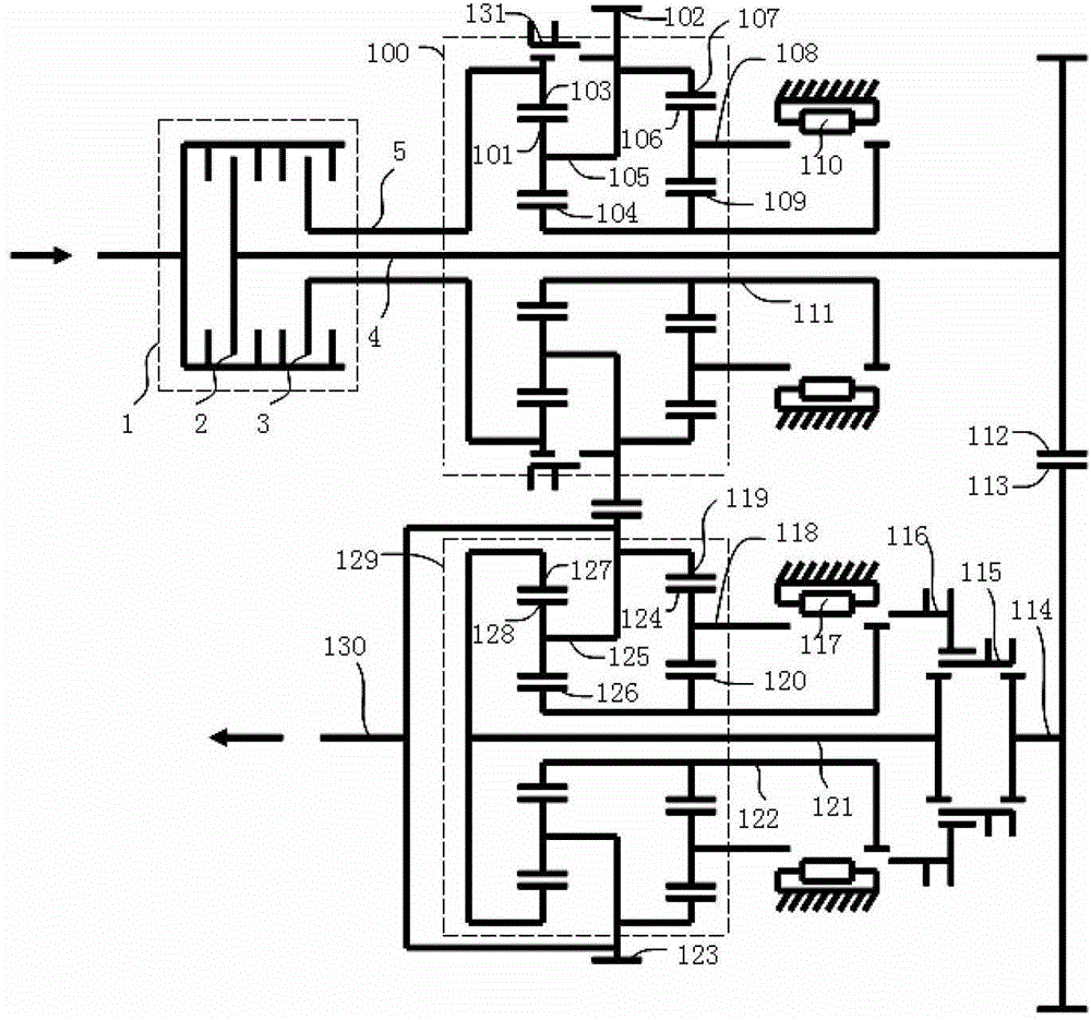
[0056] see Figure 1 to Figure 8 , the dual clutch of the present invention includes a dual clutch assembly 1 (comprising a first clutch 2 and a second clutch 3, a first input shaft 4 and a second input shaft 5 corresponding to the two clutches respectively, a first double-row planetary gear train 100, a second Two double-row planetary gear trains 129, an output shaft 130 and multiple synchronizers. The first double-row planetary gear train and the second double-row planetary gear train are arranged up and down, both of which are Simpson gear transmission mechanisms. The double-row planetary gear train includes two single-row planetary gear mechanisms at the front and rear. The front sun gear 104 and the rear sun gear 109 of the first double-row planetary gear train mesh with the front planetary gear 101 and the rear planetary gear 106 respectively. The gear train is connected to the second clutch 3 through the second input shaft 5, the second input shaft 5 is sleeved on the f...

no. 2 example

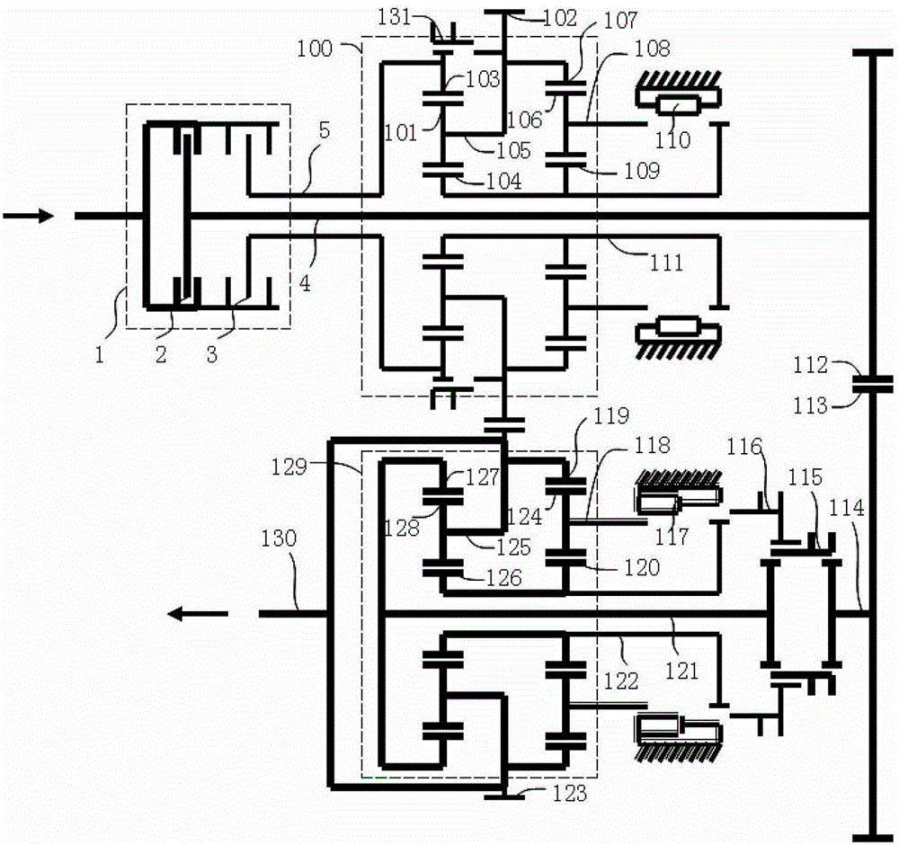
[0072] see Figure 9 , the output shaft is coaxial with the first double-row planetary gear train. The first double-row planetary gear train and the second double-row planetary gear train are both Simpson gear transmission mechanisms. The first double-row planetary gear train and the second double-row planetary gear train are arranged on the right side of each synchronizer, and the output shaft is fixed. On the first gear, the third and fourth gears are arranged on the left side of each synchronizer, and the third gear is fixedly connected with the second input shaft.

[0073] A sixth-speed synchronizer is arranged between the first input shaft 4 and the first sleeve, and the first synchronizer (second and fourth-speed synchronizer 110) is arranged between the front planet carrier 105 and the first shaft in the first double-row planetary gear train. Between sets of 111. The second synchronizer (first and third gear synchronizer 117 ) is arranged between the front planetary c...

no. 3 example

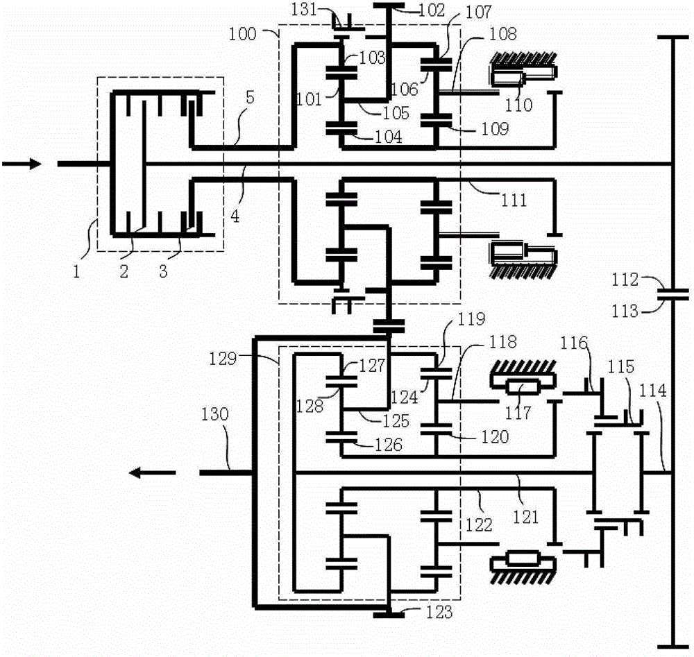
[0076] see Figure 10 , the output shaft is coaxial with the second double-row planetary gear train. The first double-row planetary gear train and the second double-row planetary gear train are both Simpson gear transmission mechanisms. The first double-row planetary gear train and the second double-row planetary gear train are arranged on the right side of each synchronizer, and the output shaft is fixed. On the second gear, the third and fourth gears are arranged on the left side of each synchronizer, and the third gear is fixedly connected with the second input shaft.

[0077] A sixth-speed synchronizer is arranged between the first input shaft 4 and the first sleeve, and the first synchronizer (second and fourth-speed synchronizer 110) is arranged between the front planet carrier 105 and the first shaft in the first double-row planetary gear train. Between sets of 111. The second synchronizer (first and third gear synchronizer 117 ) is arranged between the front planetar...


PUM


Abstract

The invention discloses a double-clutch transmission device, comprising a first clutch, a first input shaft corresponding to the first clutch, a second clutch, a second input shaft to the second clutch, a synchronizer and an output shaft, and further comprising a first double-row planetary wheel system, a second double-row planetary wheel system, a first gear, a second gear, a third gear and a fourth gear, wherein the first gear and the second gear are mutually meshed, the third gear and the fourth gear are mutually meshed, the second input shaft is sleeved on the first input shaft, the first gear is fixed to a planetary frame of one row of planetary mechanisms in the first double-row planetary wheel system and is also fixed to a gear ring of the other row of planetary mechanisms in the first double-row planetary wheel system, the second gear is fixed to a planetary frame of one row of planetary mechanisms in the second double-row planetary wheel system and is also fixed to a gear ring of the other row of planetary mechanisms in the second double-row planetary wheel system, the third gear is fixedly connected with the first input shaft or the second input shaft, the fourth gear is fixedly connected with a middle shaft or a connection shaft of the second double-row planetary wheel system, and the output shaft is fixedly connected with the first gear or the second gear. The double-clutch transmission device disclosed by the invention can reduce the floor space of a gearbox and the production cost.

Description

technical field [0001] The invention relates to the technical field of automobile transmissions, and more specifically relates to an automatic transmission with dual clutches. Background technique [0002] The output speed of the automobile engine is very high, and the maximum power and maximum torque appear in a certain speed range. In order to give full play to the best performance of the engine, there must be a transmission device to coordinate the engine speed and the actual speed of the wheels. The function of the automobile transmission is to change the transmission ratio, expand the range of torque and speed of the driving wheel to adapt to changing driving conditions, and at the same time make the engine work under favorable (higher power and lower fuel consumption) conditions. Secondly, under the condition that the rotation direction of the engine remains unchanged, the car can be driven backwards. According to the type of wheel train used, there are two types of ...

Claims


Application Information

Patent Timeline
Patent Type & Authority Patents(China)
IPC IPC(8): F16H3/46
Inventor 赵良红
Owner 赵良红
Learn More