
Division and convergent current type multiple-shift automatic transmission system

A technology of automatic shifting and sub-convergence, which is applied in the direction of transmission, gear transmission, transmission control, etc., to achieve power shifting performance, improve power and fuel economy, and facilitate processing and manufacturing.

Inactive Publication Date: 2010-08-11
SOUTH CHINA UNIV OF TECH
View PDF0 Cites 0 Cited by
  • Summary
  • Abstract
  • Description
  • Claims
  • Application Information

AI Technical Summary

Problems solved by technology

[0007] The purpose of the present invention is to overcome the shortcomings of the existing dual-clutch transmission, to provide a split-merge multi-speed transmission that achieves more speed ratios with a very small number of gear pairs, and at the same time makes it have the advantages of power shifting of the dual-clutch automatic transmission. automatic transmission system

Method used


Image

  • Division and convergent current type multiple-shift automatic transmission system
  • Division and convergent current type multiple-shift automatic transmission system
  • Division and convergent current type multiple-shift automatic transmission system

Examples


Embodiment 1

[0033] Embodiment 1: Transformation of the transmission of the dual-clutch automatic transmission car with five forward gears

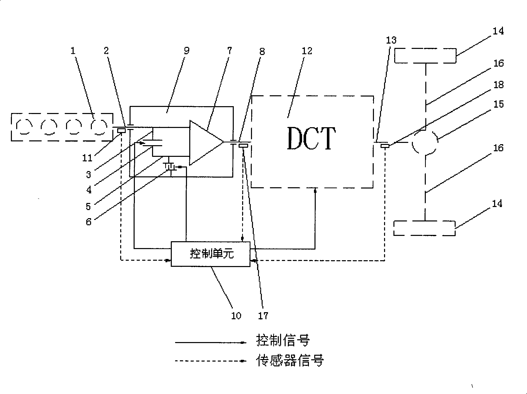
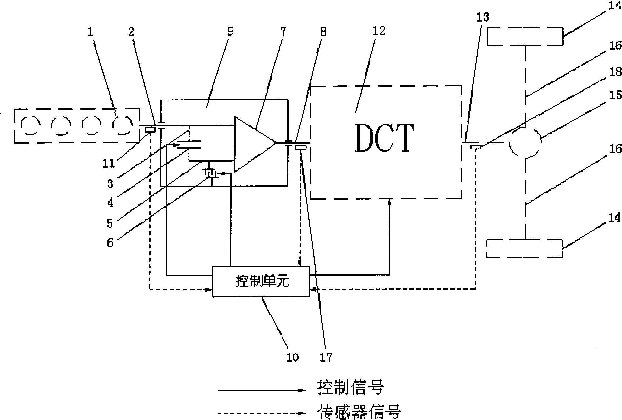
[0034]As shown in Figure 2: a sub-convergence mechanism 9 is added between the engine and the DCT system of the dual-clutch automatic transmission car with five forward gears, including a single planetary planetary mechanism 7, a brake 6 and a clutch 4. Among them, the planet carrier of the planetary mechanism 7 is connected with the input shaft 8 of the DCT system, the sun gear of the planetary mechanism 7 is directly connected with the engine output shaft 2, the ring gear of the planetary mechanism 7 is connected with the clutch 4, and the clutch 4 is output through the transmission shaft 3 and the engine. The shaft 2 is connected, the brake 6 is connected with the ring gear of the planetary mechanism 7 through the transmission shaft 5, and is used to control the movement of the ring gear. The engine 1 is connected to the engine output shaft 2 . Th...

Embodiment 2

[0056] Embodiment 2: Another transformation of the transmission of the dual-clutch automatic transmission car with five forward gears

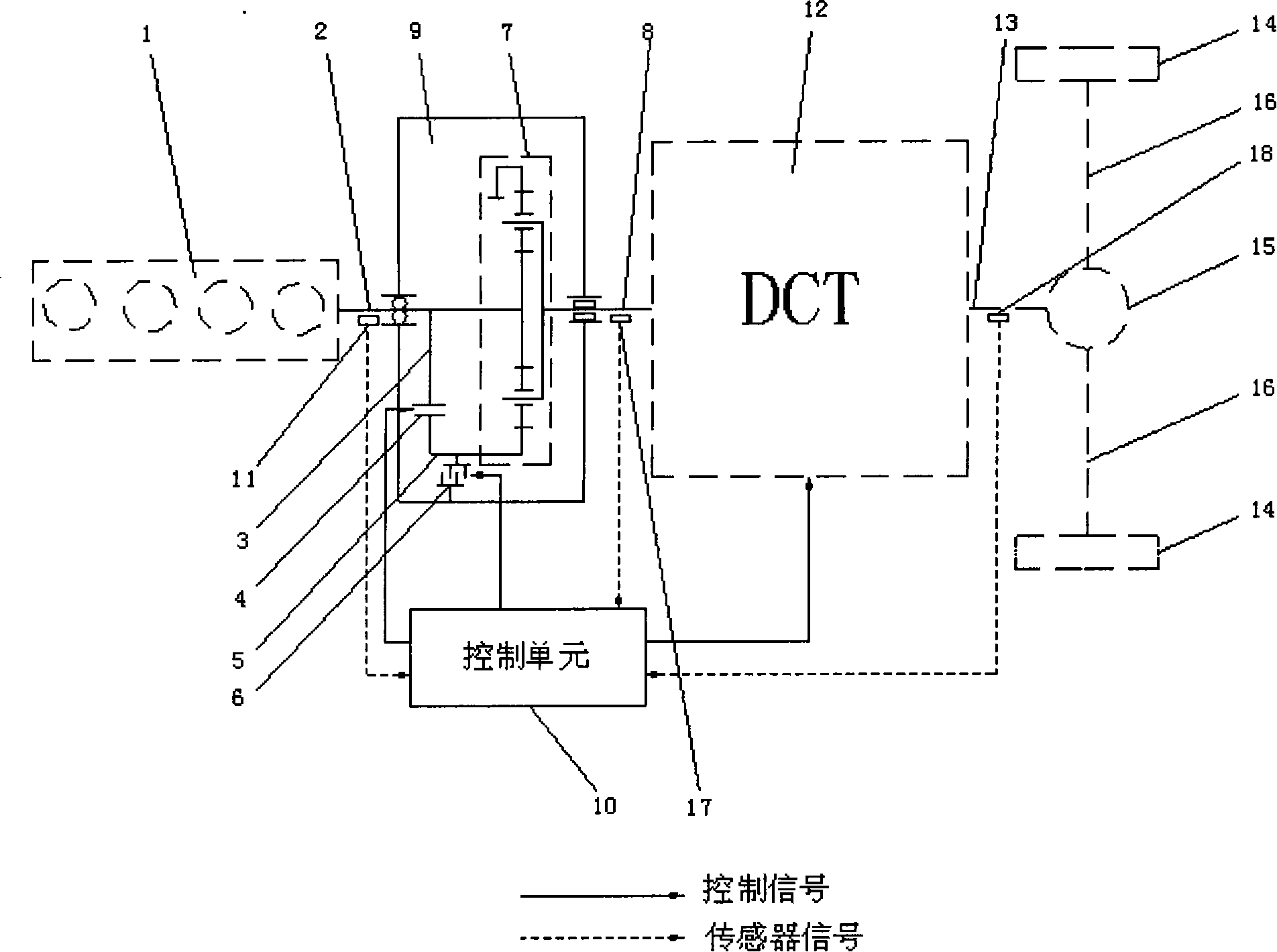
[0057] As shown in Figure 3: carry out another kind of form transformation on the speed changer of the double-clutch formula automatic transmission car of a five forward gears. Its structural arrangement is basically the same as that in Figure 2, except that the connection mode of the two input ends of the planetary mechanism is changed. The engine output shaft 2 is directly connected to the ring gear of the planetary mechanism 7, one end of the clutch 4 is connected to the sun gear, the other end is connected to the engine output shaft, and the brake 6 is connected to the sun gear to control the motion state of the sun gear; the planetary mechanism 7 The planet carrier is connected with the input shaft 8 of the DCT system. The working principle of this implementation example is basically the same as that of Embodiment 1, and will not be repe...


PUM


Abstract

The invention discloses a distributary and conflux type multi-speed automatic transmission system. A distributary and conflux mechanism is arranged between an engine and a DCT system in the multi-speed automatic transmission system. The ditributary and conflux mechanism comprises a planet mechanism, an arrester and a clutch; the engine is respectively connected with a sun gear and a gear ring of the planet mechanism through an output shaft of the engine, the clutch and the arrester are arranged on the transmission shaft connecting the output shaft of the engine and the sun gear or the gear ring of the planet mechanism, and the planet carrier of the planet mechanism is connected with an input shaft of the DCT system. The transmission can realize 2 multiply (m plus n) gear positions with (mplus n) pairs of gear pairs by the matching use of the planet mechanism, the clutch and the arrester, wherein, m is the number of gear teeth of an intermediate shaft in the DCT system and n is the number of gear teeth of another intermediate shaft thereof. Simultaneously, the automatic transmission can realize power shift by putting into gear in advance.

Description

technical field [0001] The invention relates to an automatic transmission system in a mechanical transmission system, in particular to a split-confluence type multi-speed automatic transmission system. technical background [0002] The three important research directions of today's vehicle automatic transmission technology are: hydromechanical automatic transmission, namely AT (Automated Transmission); continuously variable transmission, namely CVT (Continuously Variable Transmission); electromechanical automatic transmission, namely AMT (Automated Transmission). Mechanical Transmission). [0003] The earliest automatic transmission on a car is the hydromechanical automatic transmission (AT), which is currently the most widely used automatic transmission for automobiles. AT has the advantages of non-cutting power shifting, smooth start, and torque converter adaptive to resistance, but has disadvantages such as complex structure, high manufacturing process requirements, and ...

Claims


Application Information

Patent Timeline
Patent Type & Authority Patents(China)
IPC IPC(8): F16H37/04F16H3/44F16H3/10F16H61/00
Inventor 罗玉涛谭迪
Owner SOUTH CHINA UNIV OF TECH
Learn More