

Self-locking looseness-proof pipe clamp
An anti-loosening and self-locking technology, applied in the direction of pipe brackets, locking fasteners, pipes/pipe joints/fittings, etc., can solve the problems of heavy, cumbersome fastening pipe clamps, etc., and achieve convenient installation and reliable fixation , strong substitution effect
- Summary
- Abstract
- Description
- Claims
- Application Information
AI Technical Summary
Problems solved by technology
Method used
Image

Examples
Embodiment Construction
[0018] The present invention will be described in further detail below in conjunction with the accompanying drawings and specific embodiments.
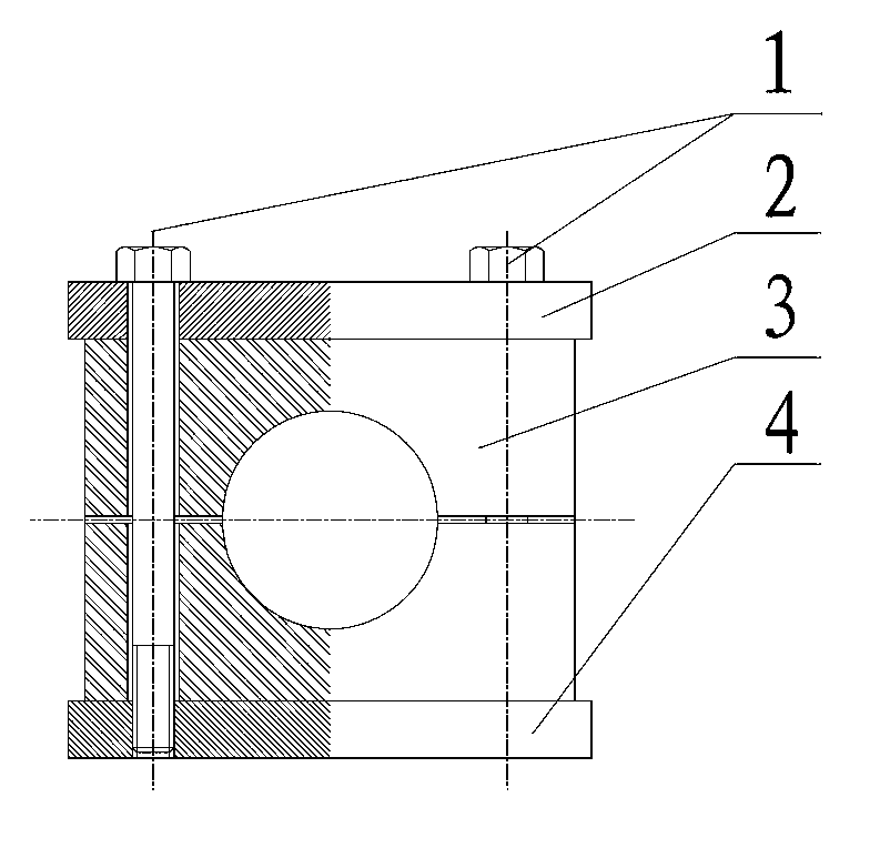
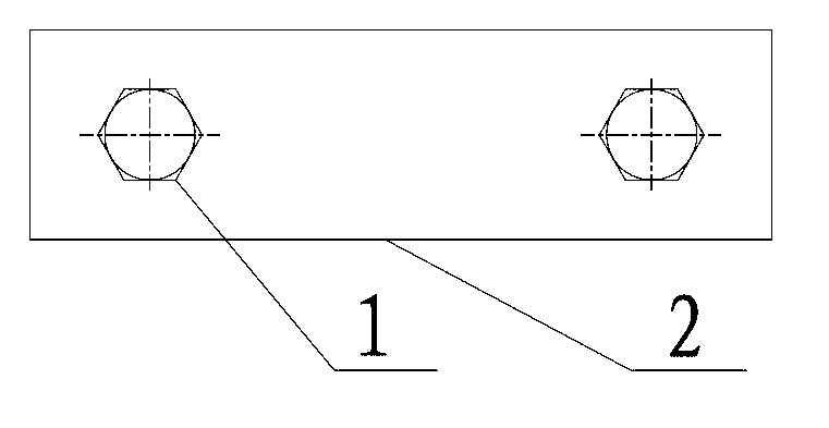
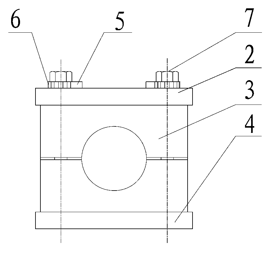
[0019] image 3 and Figure 4 shows a schematic structure of a preferred embodiment of the present invention, Figure 5 and Figure 6 Then the structure of the fixing bolt 7 and the ratchet 6 is shown. As shown in the figure, the preferred embodiment includes the fixing bolt 7, the upper fixing plate 2, the support block 3, the lower fixing plate 4, the ratchet 5 and the ratchet 6. The support block 3 is composed of symmetrical upper and lower parts, and the round hole in the middle is used to fix the pipeline (in fact, the upper and lower parts are also asymmetrical. When the edges are joined together, the respective depressions of the upper and lower parts are combined into holes for fixing the pipeline), the lower fixing plate 4 is generally welded on the field support surface, the fixing bolt 1 passes through the upper fixing p...
PUM
 Abstract
Description
Claims
Application Information