Light-splitting WDM device structure

A device structure and optical splitting technology, which is applied in the field of optical fiber communication, can solve the problems affecting the normal use of products, poor performance, long production cycle, etc., achieve good splitting effect, reduce manufacturing costs, and avoid the effects of using

Inactive Publication Date: 2012-11-28
无锡爱沃富光电科技有限公司
View PDF3 Cites 4 Cited by
  • Summary
  • Abstract
  • Description
  • Claims
  • Application Information

AI Technical Summary

Problems solved by technology

[0003] Most of the current spectroscopic WDM devices adopt a diaphragm structure, and the fiber pigtails, lenses, and filters are glued and fixed by UV-cured glue, and the device directly splits light through the filter. Low, poor performance, affecting the normal use of the product

Method used


Image

  • Light-splitting WDM device structure
  • Light-splitting WDM device structure

Examples


Embodiment Construction

[0011] The specific embodiments of the present invention will be further described below in conjunction with the accompanying drawings.

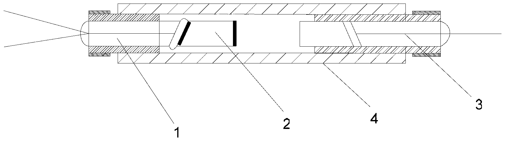
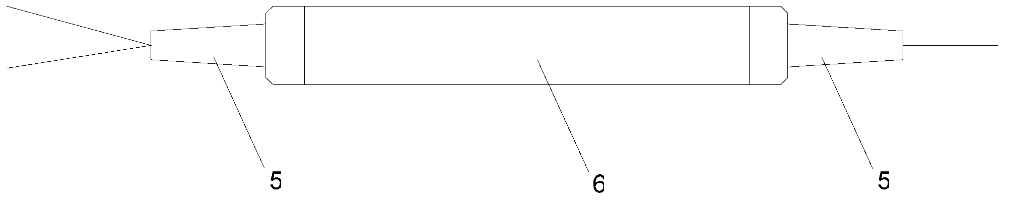
[0012] Such as figure 1 , figure 2 As shown, the present invention is composed of a double-fiber-ended fiber pigtail 1 , a lens 2 , a collimator 3 , a glass tube 4 , a sheath 5 and a steel tube 6 . The double-fiber-ended fiber pigtail 1 and the lens 2 are fixed together by UV-curable glue to form a reflective end. The two ends of the lens 2 are coated with a light-splitting film ( figure 1 The black parts at the left and right ends of the middle lens 2). Fix the reflection end, collimator 3 and glass tube 4 with UV curable glue. Then the above-mentioned whole structure is fixed in the steel pipe 6 with silica gel, and the sheath 5 is installed at both ends of the steel pipe 6, and the reflective end and the collimator respectively extend out of the optical fiber from the two sheaths to form the light-incoming end and the light-outgoing ...


PUM


Abstract

The invention provides a light-splitting WDM device structure, comprising a double-fiber end optical fiber pigtail, a lens, a collimator, a glass tube, a sheath and a steel tube. The double-fiber end optical fiber pigtail and the lens are fixed through UV solidifying glue to form a reflecting end, and two end faces of the lens are plated with spectro-film layers. The reflecting end and the collimator are fixed in the glass tube through the UV solidifying glue. The reflecting end, the collimator and the glass tube are fixed in the steel tube through silica gel. Two ends of the steel tube are provided with the sheath. The reflecting end and a fiber of the collimator respectively extend from the sheath. Light-splitting WDM device structure is simple and reasonable, and has good light splitting effect. A filter is not needed since the spectro-film is plated on the lens, thereby reducing manufacture cost.

Description

technical field [0001] The invention relates to the field of optical fiber communication, in particular to a light-splitting WDM device in the field of optical fiber communication. Background technique [0002] Optical WDM (Wavelength Division Multiplexing) devices, as one of the most basic components of optical passive devices, have been widely used in wavelength division multiplexing optical fiber communication systems. Its function is to separate and transmit the light of multiple wavelengths in the line separately, or to transmit the light of multiple wavelengths together. [0003] Most of the current spectroscopic WDM devices adopt a diaphragm structure, and the fiber pigtails, lenses, and filters are glued and fixed by UV-cured glue, and the device directly splits light through the filter. Low, poor performance, affecting the normal use of the product. Contents of the invention [0004] The object of the present invention is to provide a light-splitting WDM device ...

Claims


Application Information

Patent Timeline
Patent Type & Authority Applications(China)
IPC IPC(8): G02B6/293G02B6/32
Inventor 杨晓丹徐红艳陈德良
Owner 无锡爱沃富光电科技有限公司
Why Eureka
Try Eureka