Check patentability & draft patents in minutes with Patsnap Eureka AI!

Dummy pattern and method for forming same

A dummy pattern and pattern technology, applied in the field of dummy patterns and formation of dummy patterns, can solve problems such as insufficient stress resistance, decreased improvement effect of dummy pattern pattern density difference, limited improvement effect of dummy pattern pattern density difference, etc., to achieve uniform pattern density , to improve the effect of flattening results

Active Publication Date: 2012-11-28
UNITED MICROELECTRONICS CORP
View PDF7 Cites 19 Cited by
  • Summary
  • Abstract
  • Description
  • Claims
  • Application Information

AI Technical Summary

Problems solved by technology

Although the dummy pattern can improve the density difference between the low pattern density area and the high pattern density area, but with the complexity of integrated circuit design, more areas with different pattern densities are distributed on the wafer, so that the dummy pattern can improve the pattern density difference The effect is limited, and even the improvement effect of the dummy pattern on the pattern density difference is reduced
In addition, the known dummy patterns still have disadvantages such as insufficient resistance to stress generated between regions with different pattern densities on the substrate, elongated optical proximity correction (OPC), etc.

Method used


Image

  • Dummy pattern and method for forming same
  • Dummy pattern and method for forming same
  • Dummy pattern and method for forming same

Examples


Embodiment Construction

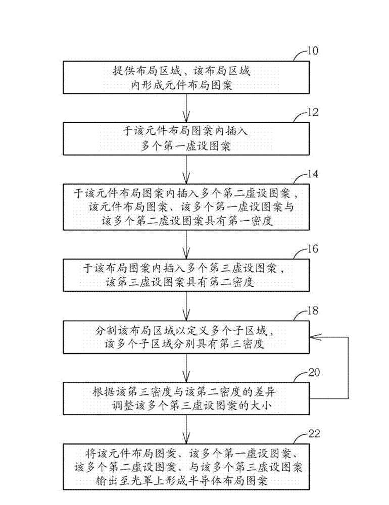
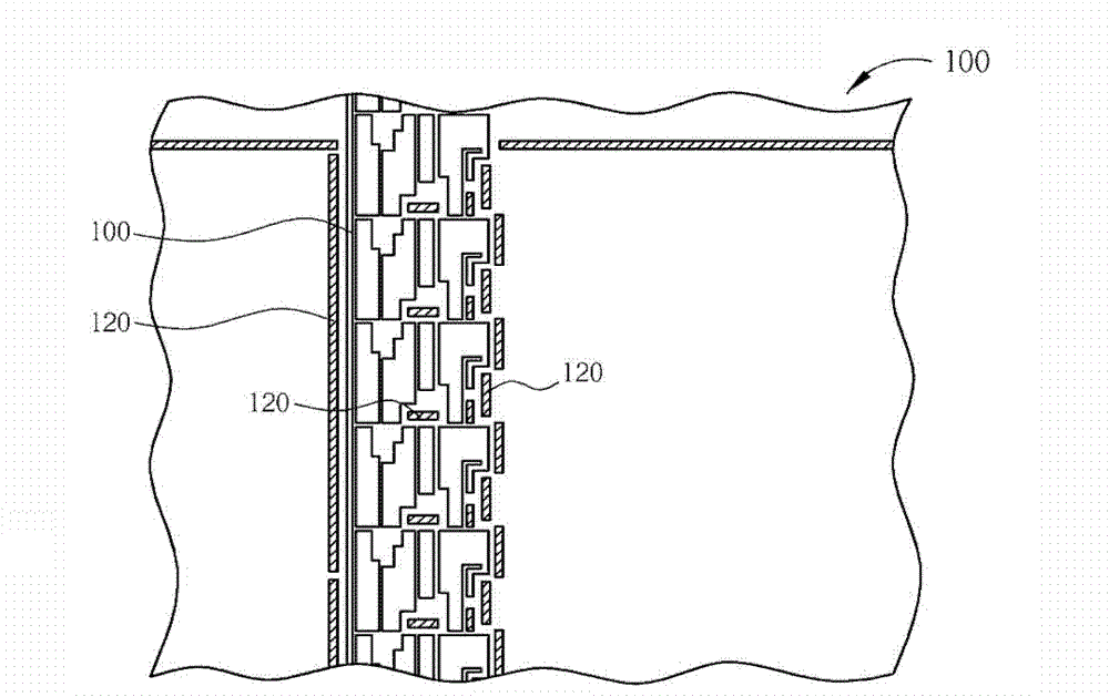
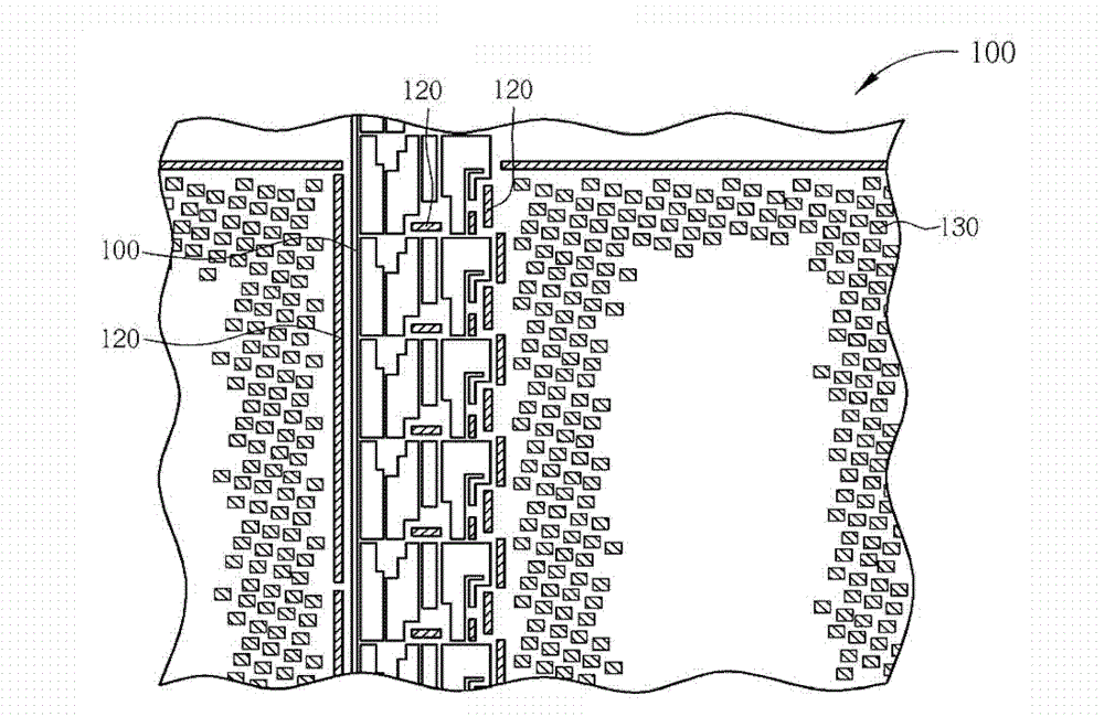
[0023] see Figure 1 to Figure 8 ,in figure 1 It is a flow chart of the first preferred embodiment of the method for forming dummy patterns provided by the present invention, Figure 2 to Figure 8 It is a schematic diagram of the first preferred embodiment of the method for forming dummy patterns provided by the present invention, Figure 5 then Figure 4 A partially enlarged schematic diagram. Such as figure 1 and figure 2 Shown, this preferred embodiment first carries out:

[0024] Step 10: providing a layout area in which a component layout pattern is formed.

[0025] Those skilled in the art should know that when making an integrated circuit, the original circuit layout pattern provided by the circuit design engineer is formed on the photomask, and then the pattern on the photomask is transferred to the target through the photolithography and etching process. Only on the film layer can the chip products that meet the circuit design function be manufactured. In thi...


PUM


Abstract

The invention discloses a dummy pattern and a method for forming the same. The method comprises the following steps of: supplying an arrangement region, wherein the arrangement region comprises an arrangement pattern which has a first density; a plurality of first dummy patterns are inserted into the arrangement pattern and have second densities; the second densities correspond to the first density; the arrangement region is partitioned to define a plurality of sub regions; the sub regions have third densities; the sizes of the first dummy patterns are adjusted according to differences between the third densities and the second densities; and the arrangement pattern and the first dummy patterns are output to an optical mask.

Description

technical field [0001] The invention relates to a dummy pattern and a method for forming the dummy pattern, in particular to a dummy pattern used in a planarization process and a method for forming the dummy pattern. Background technique [0002] With the advancement of semiconductor technology, the dimensions of components in integrated circuits and the wiring connecting them continue to shrink, and in order to form fine patterns with high precision, the flatness of the substrate surface is also required to increase. In the known technology, a chemical mechanical polishing (CMP) process is often used as the main planarization process, and the grinding result of the chemical mechanical polishing (CMP) process has a great influence on the subsequently formed pattern. In detail, when a chemical mechanical polishing (CMP) process is performed, the polishing rate of the low pattern density region is higher than that of the high pattern density region. Therefore, regions with di...

Claims


Application Information

Patent Timeline
Patent Type & Authority Applications(China)
IPC IPC(8): G03F1/38G03F1/00H01L27/02
Inventor 蔡振华陈建诚蔡锦岳范耀仁陈科宏杨祥
Owner UNITED MICROELECTRONICS CORP
Features
  • R&D
  • Intellectual Property
  • Life Sciences
  • Materials
  • Tech Scout
  • Unparalleled Data Quality
  • Higher Quality Content
  • 60% Fewer Hallucinations
Learn More