

Safety catalyzing valve for lead-acid storage battery
A technology of lead-acid batteries and catalytic valves, which is applied to battery pack components, secondary battery repair/maintenance, circuits, etc., to achieve the effects of reduced floating charge current, high use efficiency, and convenient assembly and installation
- Summary
- Abstract
- Description
- Claims
- Application Information
AI Technical Summary
Problems solved by technology
Method used
Image

Examples
Embodiment Construction
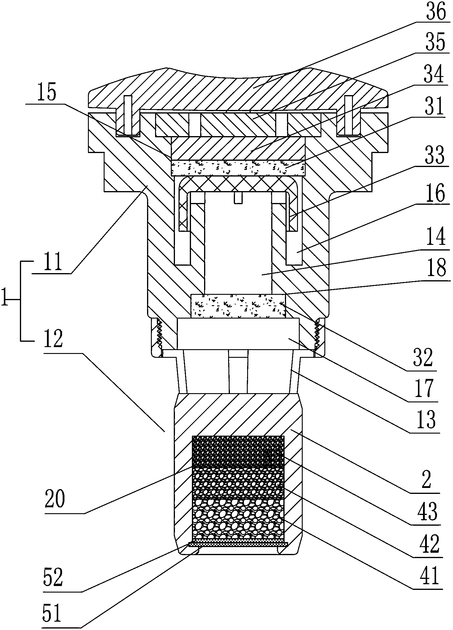
[0023] Refer to attached figure 1 . The present invention includes a valve body 1, the upper part 11 of the valve body is hollow, and the air pressure safety device of the lead-acid battery is installed in the upper part, so that when the pressure in the battery exceeds the safe value, the gas in the battery can be discharged in time . The lower part 12 of the valve body 1 is provided with a catalyst mounting seat 2, and a vent hole 13 communicating with the air pressure safety device is provided between the mounting seat 2 and the air pressure safety device; the mounting seat 2 is provided with a catalyst mounting hole 20 The catalyst that catalyzes the reaction of hydrogen and oxygen to produce water is installed in the installation hole 20, and a filter layer is arranged outside the catalyst; the valve body is installed on the battery cover.
[0024] When the gas pressure inside the battery is lower than the safe value, the gas inside the battery can generate water throug...
PUM
| Property | Measurement | Unit |
|---|---|---|
| Aperture | aaaaa | aaaaa |
| Aperture | aaaaa | aaaaa |
| Specific surface area | aaaaa | aaaaa |
Abstract
Description
Claims
Application Information