Redundant protection circuit of photovoltaic grid-connected inverter and inverter including the same

A redundant protection and inverter technology, which is applied in emergency protection circuit devices, photovoltaic power generation, irreversible DC power input conversion to AC power output, etc., can solve the problems of high production costs and operation and maintenance costs, and achieve low operating costs. Effects of maintenance costs and increased production costs

Inactive Publication Date: 2014-10-08
ANHUI KETONG ENERGY TECH
View PDF4 Cites 0 Cited by
  • Summary
  • Abstract
  • Description
  • Claims
  • Application Information

AI Technical Summary

Problems solved by technology

[0009] 2. The production cost and operation and maintenance cost of the product are relatively high

Method used


Image

  • Redundant protection circuit of photovoltaic grid-connected inverter and inverter including the same
  • Redundant protection circuit of photovoltaic grid-connected inverter and inverter including the same
  • Redundant protection circuit of photovoltaic grid-connected inverter and inverter including the same

Examples


Embodiment 1

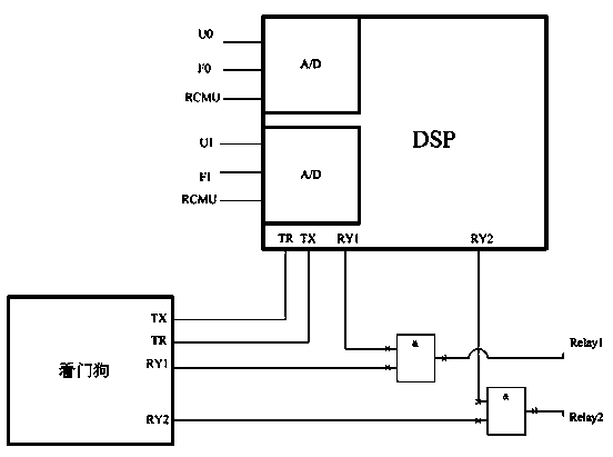
[0032] Such as Figure 5 As shown, in this embodiment, a redundant protection circuit of a photovoltaic grid-connected inverter is provided, the collector c terminal of the first triode Q0 is connected to the power supply VCC, and the gate b terminal is connected to the CPU through the first capacitor C The RY1 output terminal of the oscillation circuit module LC of the chip is connected, the emitter e terminal is grounded through the first relay RELAY1; the collector c terminal of the second triode Q1 is also connected to the power supply VCC, and the gate b terminal is connected to the DC output of the CPU chip Terminal RY2 is connected, and the emitter e terminal is grounded through the second relay RELAY2; wherein, the frequency of the AC signal output by the oscillation circuit module LC matches the rated frequency of the first capacitor C, and the above-mentioned first relay RELAY1 and second relay RELAY2 are both It can independently control the disconnection state of t...

Embodiment 2

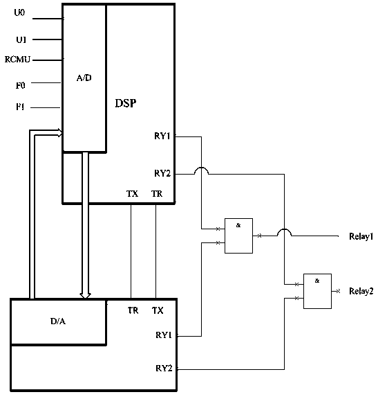
[0037] Such as Image 6 As shown, on the basis of Embodiment 1, the base of the first transistor Q0 is connected to the RY1 output terminal of the CPU chip through the first capacitor C, and the base of the second transistor Q1 is connected to the RY2 terminal of the CPU chip. connection, the first transistor Q0, the first relay RELAY1, the second transistor Q2 and the second relay RELAY2 are connected in series, and the technical effect of the first embodiment can also be achieved. For the specific connection relationship, please refer to the first embodiment, which will not be described here. Let me tell you more.

Embodiment 3

[0039] Such as Figure 7 As shown, on the basis of combining Embodiment 1, a filter circuit composed of a diode D, an inductor L and a second capacitor C1 is provided at the emitter e terminal of the first transistor Q0, wherein the first transistor Q0 The emitter e terminal is connected to the first relay RELAY1 through the diode D (the emitter e terminal of the first triode Q0 is connected to the anode of the diode D), the anode terminal of the diode D is grounded through the inductor L, and the cathode terminal of the diode D is connected to the first relay through the second relay. The second capacitor C1 is grounded; by setting the filter circuit above, the ripple in the rectified output voltage is filtered to promote the stable operation of the first triode Q0. In this embodiment, on the basis of Example 2, the first triode Q0, the first relay RELAY1, the second triode Q2 and the second relay RELAY2 are connected in series, and the emitter of the first relay RELAY1 The ...


PUM


Abstract

The embodiment of the invention discloses a redundancy protection circuit of a photovoltaic grid-connected inverter and an inverter comprising the circuit, belonging to the technical field of redundancy protection circuits. A high-frequency AC signal is output by an oscillating circuit provided by a CPU (Central Processing Unit) chip, and the on and off of a relay is controlled by using a capacitor. Under the condition of not increasing the circuit complexity level and circuit fault points, the redundancy protection of a control module is effectively realized. Meanwhile, the product production cost can also not be increased, and the operating and maintenance costs of the photovoltaic grid-connected inverter can also be effectively reduced.

Description

technical field [0001] The invention relates to a redundant protection circuit, in particular to a redundant protection circuit of a photovoltaic grid-connected inverter and an inverter including the circuit. Background technique [0002] At present, the latest photovoltaic (photovoltaic, PV) standards formulated by European countries, such as Italy's CEIO-21, ENEL2.2 and Germany's VDE4105, all require that the control part of the photovoltaic inverter (PV Inverter) must use redundant circuits. That is, when the main control CPU fails, the redundant circuit can ensure that the relay (relay) connected to the power grid is cut off; in the prior art, dual CPU backup redundant circuits are generally used, and a watchdog module or D / A conversion module is added. In order to realize the redundant protection of the photovoltaic inverter. [0003] figure 1 It is a schematic circuit diagram of the redundant protection of the photovoltaic inverter by adopting dual CPU backup redunda...

Claims


Application Information

Patent Timeline
Patent Type & Authority Patents(China)
IPC IPC(8): H02M7/42H02H7/122
CPCY02E10/56
Inventor 韦敏卢方
Owner ANHUI KETONG ENERGY TECH
Why Eureka
Try Eureka