Ethern passive light network redundancy protection system using optical power detection and its implementing method

A passive optical network, redundant protection technology, applied in the field of Ethernet passive optical network redundancy protection system, can solve problems such as affecting system reliability, EPON application bottleneck, existence of single point failure, etc., to achieve fast redundant protection, Achieve the effect of low cost and stable system

Active Publication Date: 2010-11-17
广东科盾信息安全技术有限公司
View PDF2 Cites 0 Cited by
  • Summary
  • Abstract
  • Description
  • Claims
  • Application Information

AI Technical Summary

Problems solved by technology

[0011] The basic network topology of EPON is a point-to-multipoint tree structure, and there is a hidden danger of single point failure, which affects the reliability of the system
Therefore, for practical applications, especially in fields that require high real-time performance, reliability and stability, such as the field of industrial automation control, EPON has an application bottleneck

Method used


Image

  • Ethern passive light network redundancy protection system using optical power detection and its implementing method
  • Ethern passive light network redundancy protection system using optical power detection and its implementing method
  • Ethern passive light network redundancy protection system using optical power detection and its implementing method

Examples


Embodiment Construction

[0022] The preferred embodiments of the present invention and their implementation methods will be described in detail below in conjunction with the accompanying drawings.

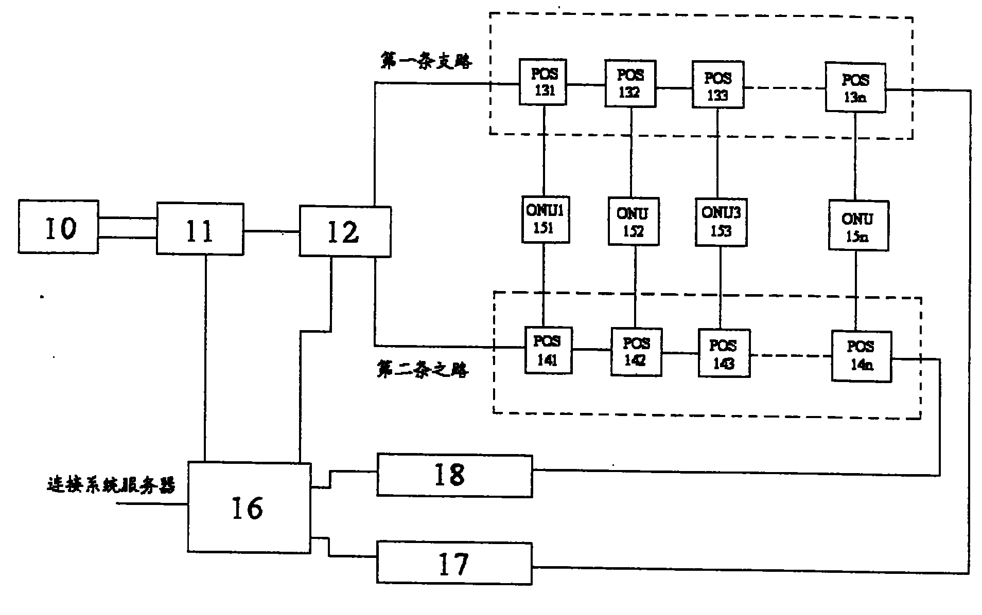
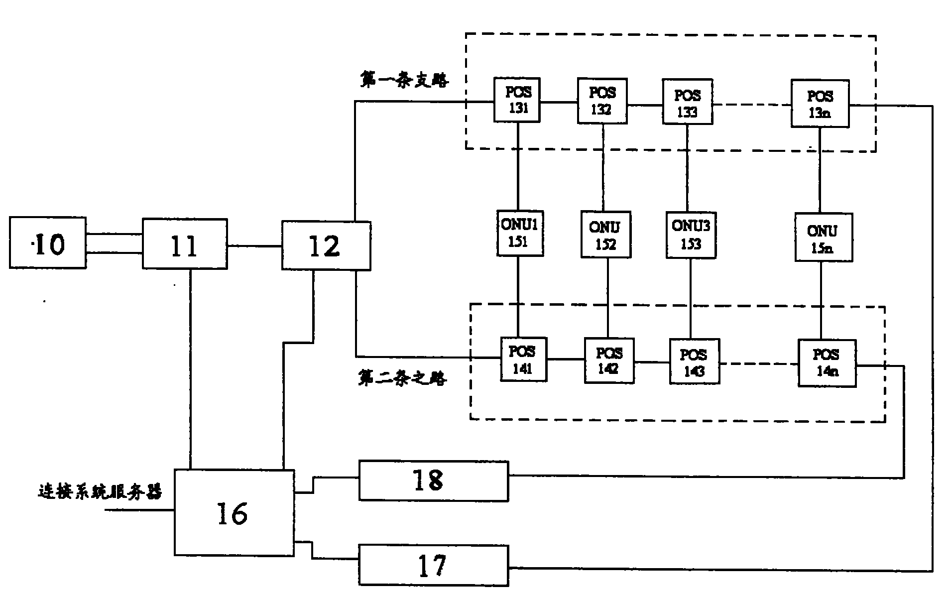
[0023] figure 1 It is a schematic diagram of an Ethernet passive optical network redundancy protection system using optical power detection according to a preferred embodiment of the present invention. refer to figure 1, OLT10, two ports of which are connected to the first optical switch 11 through two optical fibers, such a connection mode can provide redundant protection for the OLT port and the optical fiber link. The first optical switch 11 is connected to the second optical switch 12, and the second optical switch 12 is respectively connected to the first POS 131 and 141 in the two groups of POS through optical fibers. The optical switches 11 and 12 are both 1×2 optical switches, which are used to switch the paths of two optical signals. Two groups of POS respectively include several POS 13i (i=1, ...


PUM


Abstract

This invention relates to a structure of Ethernet passive optical network redundant protection by optical power detection including an OLT, a first optical switch and a second optical switch, at least two sets of POS, several ONU, at least two optical power detection modules and a control module, in which, the first optical switch is connected with at least two ports of the OLT, the first opticalswitch is connected with the second optical switch, which is connected with several sets of POS, each ONU is connected with the first POS in each group correspondingly, every optical detection moduleis connected with the last POS in each set of POS correspondingly, the control module is connected with the system server, the optical detection module and two optical switches, and several fiber branches connected with the second optical switch constitute a redundant protection structure, several OLT ports and several fiber links from the OLT to the first optical switch constitute a redundant structure too.

Description

field of invention [0001] The invention relates to the redundancy protection of Ethernet, in particular to an Ethernet passive optical network (EPON) redundancy protection system using optical power detection and its realization method. Background technique [0002] With the continuous improvement of IP (Internet Protocol) technology, IP technology has been used as the main bearer technology of data network. A large number of access technologies based on Ethernet technology have also been derived from this, and the concept of Ethernet over PON (Ether Passive Optical Network) that combines simple and economical Ethernet technology with the transmission structure of PON (Passive Optical Network), Since 2000, it has attracted extensive attention from the technical circles and network operators. In December 2000, the IEEE (Institute of Electrical and Electronics Engineers) 802.3 working group established a special working group EFM (Ethernet in the First Mible) (Ethernet in the...

Claims


Application Information

Patent Timeline
Patent Type & Authority Patents(China)
IPC IPC(8): H04B10/00H04B10/207H04Q11/00H04B10/032H04B10/071H04B10/077
Inventor 闫晓峰
Owner 广东科盾信息安全技术有限公司
Why Eureka
Try Eureka