Adaptive sectional driving DC-DC converter

A DC-DC, segmented drive technology, applied in the direction of converting DC power input to DC power output, instruments, and adjusting electrical variables, etc., can solve the problems of power tube switching frequency changes and limitations, reduce switching losses, and improve efficiency , The effect of reducing the driving loss

Inactive Publication Date: 2014-09-10
UNIV OF ELECTRONICS SCI & TECH OF CHINA
View PDF4 Cites 0 Cited by
  • Summary
  • Abstract
  • Description
  • Claims
  • Application Information

AI Technical Summary

Problems solved by technology

But these two modes have an obvious disadvantage: the switching frequency of the power tube changes with the change of the load, which limits its application in some fields, such as the RF (radio frequency) field

Method used


Image

  • Adaptive sectional driving DC-DC converter
  • Adaptive sectional driving DC-DC converter
  • Adaptive sectional driving DC-DC converter

Examples


Embodiment

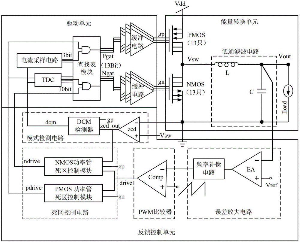
[0033] In this example, the structure of the self-adaptive segmented drive DC-DC converter is as follows: image 3 As shown, the number of power transistors in the switching conversion circuit is 13 PMOS power transistors and 13 NMOS power transistors, and the gate signals gp and gn output by the drive unit have 13 states respectively, which can control the opening and closing of each power transistor respectively. That is, the case of m=13. The internal structure of the feedback control unit includes an error amplifier circuit, a PWM comparator, a dead zone control circuit, and a mode detection circuit. The error amplification circuit includes an error amplifier EA and a frequency compensation circuit. The input terminals of the error amplifier EA are respectively connected to the output voltage Vout and the reference voltage Vref of the energy conversion unit, and its output signal is used as an input of the PWM comparator after passing through the frequency compensation cir...


PUM


Abstract

The present invention relates to integrated circuit technology, in particular to a load self-adaptive segmented driving circuit, and its application in a step-down voltage stabilizing circuit (also called a BUCK circuit). The invention discloses an adaptive section driving DC-DC converter. The present invention uses m PMOS power tubes and NMOS power tubes connected in parallel to form a switching conversion circuit, and drives different numbers of power tubes for switching conversion according to different load currents. It reduces the power of the power tube, thereby reducing the driving loss and switching loss under light load conditions. The invention changes the drive mode of the power tube, and changes the number of power tubes turned on by detecting the change of the load current, thereby minimizing the sum of the conduction loss and the driving loss of the power tube, thereby improving the efficiency of the DC-DC converter, especially Efficiency under light load. The invention is particularly suitable for use in a step-down voltage stabilizing circuit.

Description

technical field [0001] The present invention relates to integrated circuit technology, in particular to a load self-adaptive segmented driving circuit, and its application in a step-down voltage stabilizing circuit (also called a BUCK circuit). Background technique [0002] The integrated step-down voltage converter (BUCK) circuit structure is as figure 1 As shown, it includes an energy conversion unit 1 , a drive unit 2 and a feedback control unit 3 . The energy conversion unit 1 usually includes a switch conversion circuit composed of two power transistors, a PMOS (P-channel metal oxide semiconductor) power transistor and an NMOS (N-channel metal oxide semiconductor) power transistor, figure 1 are marked as PMOS and NMOS respectively. Under the control of the output signal of the drive unit 2, the PMOS power transistor and the NMOS power transistor work in the switching state, and convert the input high-voltage direct current Vdd into a square wave signal output, and fin...

Claims


Application Information

Patent Timeline
Patent Type & Authority Patents(China)
IPC IPC(8): H02M3/156
Inventor 罗萍罗明莫易昆
Owner UNIV OF ELECTRONICS SCI & TECH OF CHINA
Why Eureka
Try Eureka