Aerial image, imaging area recognition and positioning method and device

A technology for identifying positioning and imaging areas, applied in image communication, electrical components, etc., to solve the problems of discontinuous imaging areas, affecting work efficiency, and uneven film spacing.

Inactive Publication Date: 2016-06-22
中国人民解放军海军装备研究院信息工程技术研究所
View PDF6 Cites 0 Cited by
  • Summary
  • Abstract
  • Description
  • Claims
  • Application Information

AI Technical Summary

Problems solved by technology

If you need to scan a roll of continuous film, you need to manually change the film positioning operation, which will greatly affect the work efficiency
[0004] In addition, in the actual scanning process, factors such as uneven film spacing, different light transmittance, and discontinuous imaging areas all bring difficulties to the rapid and accurate positioning of the film; Prerequisites for digitization

Method used


Image

  • Aerial image, imaging area recognition and positioning method and device
  • Aerial image, imaging area recognition and positioning method and device
  • Aerial image, imaging area recognition and positioning method and device

Examples


Embodiment 1

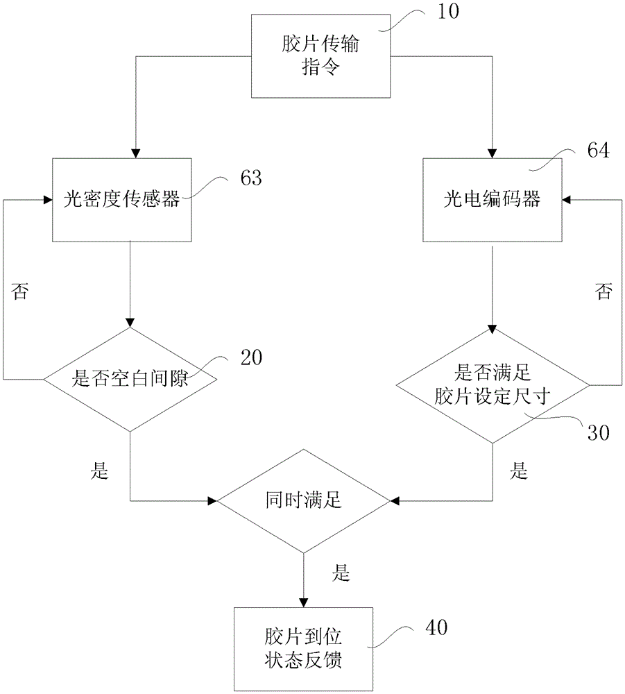
[0024] see figure 1 , which shows a preferred embodiment of an aerial image and imaging region identification and positioning method of the present invention. The identification and positioning method of the present invention includes the following steps: a film conveying step, the film conveying mechanism conveys the film to the film carrying mechanism 4 after receiving the film conveying instruction 10; then, the film blank gap judging step 20 and film setting are carried out Size judging step 30 .

[0025] Wherein, the step 20 of judging the film blank gap is to continuously detect the film imaging area and blank position in the conveying operation through a plurality of optical density sensors 63 to judge whether there is a film blank gap. If it is judged that there is a blank gap in the film, proceed to the subsequent steps; if there is no blank gap, repeat this step, and re-detect the imaging area and blank position of the film being conveyed by the optical density sens...

Embodiment 2

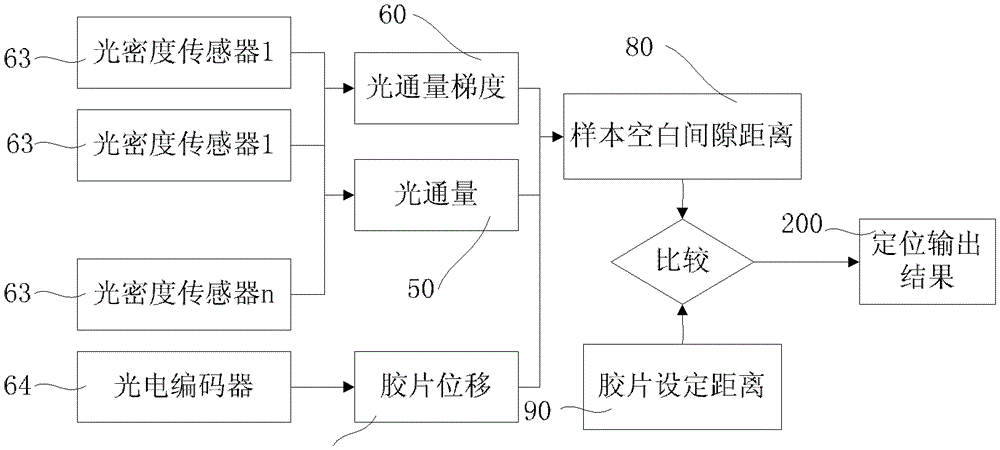
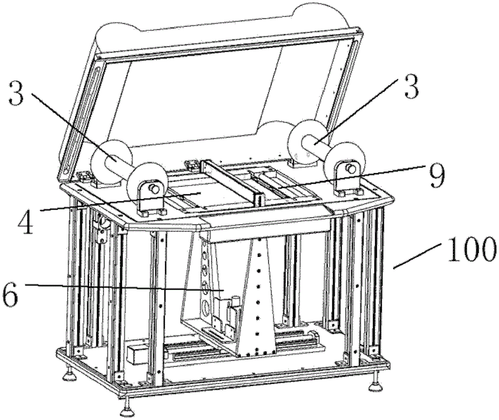
[0049] see image 3 and Figure 4 , which shows an embodiment of an aerial image and imaging area identification and positioning device of the present invention, including a body 100 with a shooting mechanism 6 and a film carrying mechanism 4, and a control unit connected with the shooting mechanism 6, the control The unit may be the overall control unit of the identification and positioning device of the present invention, or may be a control mechanism connected with or independent from the overall control unit of the identification and positioning device. The identification and positioning device of the present invention also includes a film transmission mechanism 3 that matches the size of the film carrying mechanism 4 or the size of the film in the direction of film transmission, and the film transmission mechanism includes a photoelectric encoder 64, and the film carrying mechanism 4 includes a plurality of light density sensors 63. Wherein, the photoelectric encoder 64...


PUM


Abstract

The invention relates to a method for identifying and positioning an aerial image and an imaging region. The method comprises the following steps: conveying a film, namely conveying the film to a film carrying mechanism through a film conveying mechanism; judging a blank clearance of the film, namely continuously detecting a film imaging region and a blank position during conveying and running through a plurality of light density sensors, and judging whether the blank clearance of the film exists; judging a set size of the film, namely continuously detecting whether the film meets the set size of the film through a photoelectric encoder; and feeding back an in-place state of the film, namely when the blank clearance of the film is detected to exist in the film blank clearance judging step, and if the size of the film meets the set size of the film in the film set size judging step, sending a film in-place state feedback signal to a control unit. Based on the technical scheme, aims of quickly and accurately identifying and positioning the aerial image and the imaging region can be fulfilled.

Description

technical field [0001] The invention relates to an identification and positioning method and device, in particular to an aerial image and imaging area identification and positioning method and device. Background technique [0002] Existing scanners have a certain large-format film scanning function, but in specific practical applications, they also have the following defects: [0003] Lack of effective automatic film feeding positioning function. According to the working principle of existing scanner sensors, current scanners can only scan and process single images. If it is necessary to scan a roll of continuous film, it is necessary to manually perform the film change positioning operation, which will greatly affect the work efficiency. [0004] In addition, in the actual scanning process, factors such as uneven film spacing, different light transmittance, and discontinuous imaging areas all bring difficulties to the rapid and accurate positioning of the film; Prerequis...

Claims


Application Information

Patent Timeline
Patent Type & Authority Patents(China)
IPC IPC(8): H04N1/04H04N1/047H04N1/203
Inventor 刘侃陈超周建军王日胜夏明卓陈杰雷华王智
Owner 中国人民解放军海军装备研究院信息工程技术研究所
Why Eureka
Try Eureka