
Vaporization Device

A container body and opening technology, applied in dispensing devices, packaging, transportation and packaging, etc., can solve the problems of large opening area, easy overflow of liquid medicine 201, etc., and achieve the effect of improving versatility

Inactive Publication Date: 2015-02-25
艾饰庭株式会社
View PDF4 Cites 0 Cited by
  • Summary
  • Abstract
  • Description
  • Claims
  • Application Information

AI Technical Summary

Problems solved by technology

[0006] However, this conventional dispersing device 211 has the following problem: the mouth 203 of the container body 202 is inserted into the absorbent core 205, ... so that its opening area is relatively large, so when the container body 202 falls down, the contained liquid Elixir 201 is prone to spillage

Method used


Image

  • Vaporization Device
  • Vaporization Device
  • Vaporization Device

Examples


no. 1 approach

[0042] Hereinafter, a first embodiment of the present invention will be described with reference to the drawings.

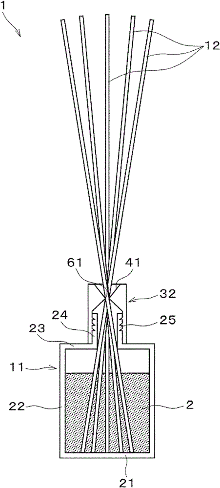
[0043] figure 1 It is a figure showing the volatilization device 1 of this embodiment, and the volatilization device 1 volatilizes liquid medicines 2 such as fragrance liquid and deodorant liquid.

[0044] The dispersing device 1 includes a container body 11 for containing the liquid medicine 2 and a plurality of absorbent cores 12 for absorbing the liquid medicine 2 contained in the container body 1 and dispersing the liquid medicine 2 .

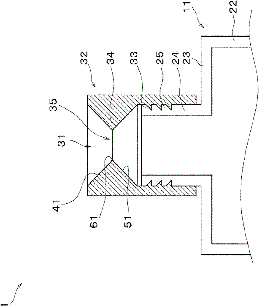
[0045] The container body 11 has a circular bottom surface 21 , and a cylindrical peripheral wall 22 extends upward from the peripheral edge of the bottom surface 21 . A shoulder 23 extends toward the center from the upper edge of the peripheral edge 22 , and a cylindrical mouth 24 extends upward from the center of the shoulder 23 . The inner diameter of the mouth portion 24 is set to a smaller value than the inner diameter...

no. 2 approach

[0077] That is, if Image 6 As shown, the detailed portion 34 may also be set at a position directly adjacent to the external threaded portion 33 so that only the inner surface of the cover 32 is formed with a slanting downward toward the opening 35 . The upper inclined surface 41. Also in this case, the same effect as described above can be obtained.

no. 3 approach

[0079] Figure 7 In order to show the schematic diagram of the dispersing device 101 of the third embodiment of the present invention, the same or equivalent parts as those of the first embodiment are attached with the same symbols and their descriptions are omitted, and only the different parts will be described.

[0080] That is, the dispersing device 101 has an assembly unit 111 installed on the mouth 24 of the container body 11, and the assembly unit 111 includes a cylindrical unit main body 112 installed on the mouth 24 and held in the unit. The held body 113 inside the main body 112 .

[0081] On the inner surface of the unit main body 112, the internal thread portion 121 screwed with the external thread portion 25 of the mouth portion 24 is integrally formed on the lower side, and on the upper side of the internal thread portion 121, a An annular shelf portion (shelf portion) 122 extending inwardly from the inner peripheral surface. A lower circular hole 123 is formed...


PUM


Abstract

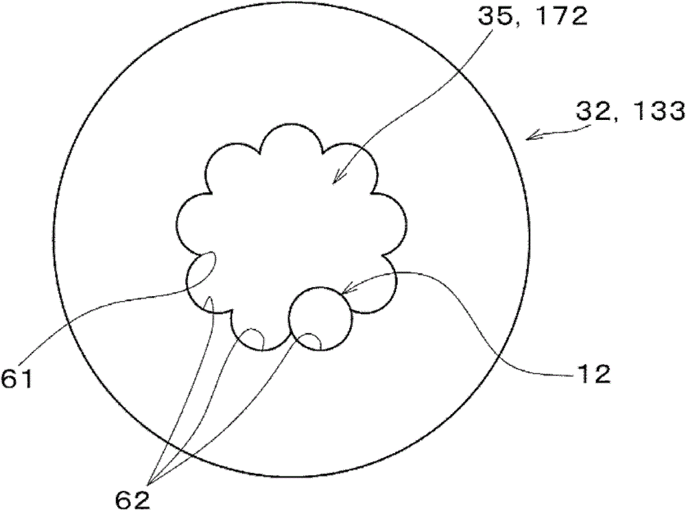
A vaporization device which facilitates the insertion of a suction wick and minimizes spilling when the vaporization device falls over. A narrow sandwiching section (34) which protrudes inward to reduce the inner diameter of a through-hole (31) is formed on a cap (32) which is mounted to the mouth (24) of a container body (11), and an opening (35) which connects to the inside of the container body (11) is formed inside the narrow sandwiching section (34). The inner diameter of the through-hole (31) is set so that the inner diameter is reduced from the upper end of the through-hole (31) toward the narrow sandwiching section (34). The upper outer periphery of the opening (35) inside the narrow sandwiching section (34) is provided with an upper sloped surface (41) sloped downward from the outer peripheral edge toward the opening (35). The opening (35) is set to a size in which a predetermined number of suction wicks (12) can be inserted.

Description

technical field [0001] The invention relates to a volatilization device for volatilizing liquid components. Background technique [0002] Conventionally, there is known a volatilization device for volatilizing liquid medicines such as fragrance liquid and deodorant liquid contained in a container body. [0003] As such a dispersing device, there is known a so-called reed diffuser type dispersing device in which a plurality of absorbent cores are inserted into the container body, and the absorbed liquid medicine is dispersed using a portion extending from the container body. [0004] like Figure 8 As shown, the reed diffuser type dispersing device includes a container body 202 containing a liquid medicine 201, and a plurality of absorbent cores 205, . [0005] Each absorbent core 205, ... is configured such that its base end reaches the bottom of the container body 202, and its front end portion extends above the mouth portion 203, and the liquid drug contained in the conta...

Claims


Application Information

Patent Timeline
Patent Type & Authority Patents(China)
IPC IPC(8): A61L9/12B65D83/00
CPCA61L9/127
Inventor 水中干士
Owner 艾饰庭株式会社
Learn More