Filter device

A filter device and closing device technology, which is applied in the direction of filtration separation, membrane filter, cartridge filter, etc., can solve the problem that the filter device cannot complete the filtering function, and achieve the effect of ensuring the closing function

Active Publication Date: 2014-11-12
MAHLE INT GMBH
View PDF6 Cites 0 Cited by
  • Summary
  • Abstract
  • Description
  • Claims
  • Application Information

AI Technical Summary

Problems solved by technology

Of course, the discharge channel must be closed when the filter unit is ready for operation, otherwise the clean side and the untreated side of the annular filter element will short-circuit each other and the filter unit will not be able to perform its filtering function

Method used


Image

  • Filter device
  • Filter device
  • Filter device

Examples


Embodiment Construction

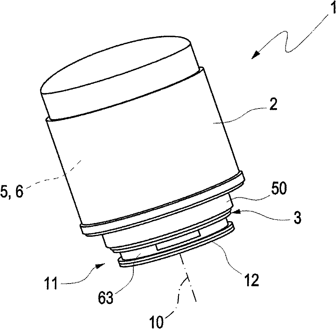
[0035] exist figure 1 , the filter device 1 can be seen from the outside. It comprises a filter housing cover 2 ; the latter forms inside it a receiving chamber 5 in which an annular filter element 6 is arranged such that it separates the untreated side from the clean side. The internal structure is a conventionally used displacement filter, which is suitable for filtering oily dirt. The middle block 3 is placed on the side of the filter device 1 facing the housing 4 . The housing 4 can be, for example, an engine cylinder housing or a cylinder housing on which the filter device 1 is firmly screwed. For reasons of simplification, it will only be referred to as housing 4 . The casing 4 is configured as follows, it comprises a dome 15 with a spiral, and an inlet channel 7, an outlet channel 8 and an outlet channel 9 (see Figure 9 ).

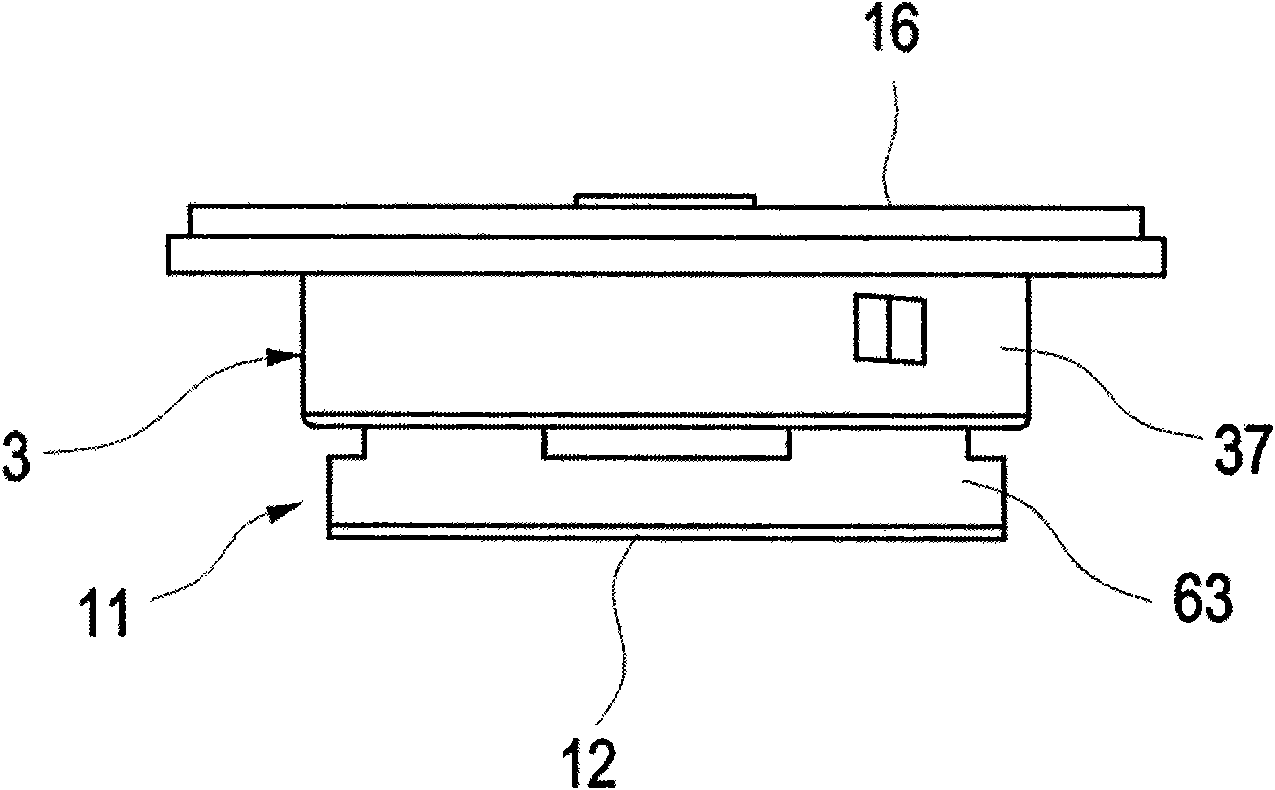
[0036] exist figure 2 In the illustration, the middle block 3 is shown, which is tightly connected with the filter housing cover 2 at the t...


PUM


Abstract

A filter may include a cover defining a chamber and an annular filter element arranged within the chamber. The filter may also include a housing and at least one intermediate piece arranged between the cover and the housing when the cover is screwed to the housing. An inlet duct may be in communication with an untreated side of the filter element and an outlet duct may be in communication with a clean side of the filter element. A drainage duct may be arranged in the housing for draining the chamber during removal of the cover. A closure device may be arrange in the intermediate piece and have a closure element configured to close the drainage duct.

Description

technical field [0001] The present invention relates to a filter device for liquids, in particular to an oil filter for cleaning lubricating oil used in internal combustion engines of automobiles. Background technique [0002] Filter devices, in particular filter devices for oil filters for automotive internal combustion engines, generally comprise a so-called annular filter element, by means of which the liquid flowing through the filter device is filtered. Periodically, the annular filter element has to be replaced in order to be able to ensure the filtering effect of the filter device. By removing the filter device from the housing, the annular filter element is also removed at the same time. Due to ever-increasing environmental regulations, the replacement of annular filter elements must ensure that no liquid, especially oil, enters the environment. For this purpose, in addition to an inlet duct communicating with the untreated side of the annular filter element and an...

Claims


Application Information

Patent Timeline
Patent Type & Authority Patents(China)
IPC IPC(8): B01D27/10B01D35/153F01M11/03F01M11/04
CPCB01D2201/4076B01D2201/4023F01M2001/1064F01M11/03B01D35/153B01D27/106B01D35/16B01D35/005
Inventor 马库斯·希尔施马尔科·施蒂费尔袁张
Owner MAHLE INT GMBH
Why Eureka
Try Eureka