Holding device for visually inspecting a tire

A tire, centering device technology, used in the manufacture of tires, the field of visual inspection of tires

Active Publication Date: 2012-11-28
MICHELIN & CO CIE GEN DES ESTAB MICHELIN
View PDF5 Cites 16 Cited by
  • Summary
  • Abstract
  • Description
  • Claims
  • Application Information

AI Technical Summary

Problems solved by technology

The second disadvantage comes from immobilizing the retaining knuckles relative to the bead and preventing those parts of the bead against which the retaining knuckles rest are imaged

Method used


Image

  • Holding device for visually inspecting a tire
  • Holding device for visually inspecting a tire
  • Holding device for visually inspecting a tire

Examples


Embodiment Construction

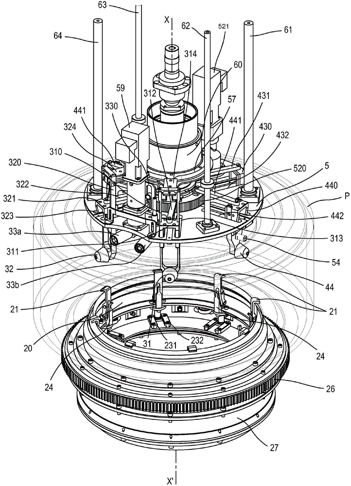
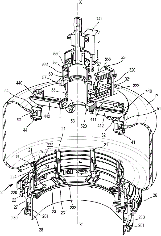
[0023] figure 1 and figure 2 The device in shows the main components forming the device according to the preferred embodiment of the invention.

[0024] In this illustration, a tire P with axis XX' is mounted on a centering device 2 . This centering device comprises a rim 20 shaped to accommodate the level of a seat 25 for receiving the first bead B1 of the tire P.

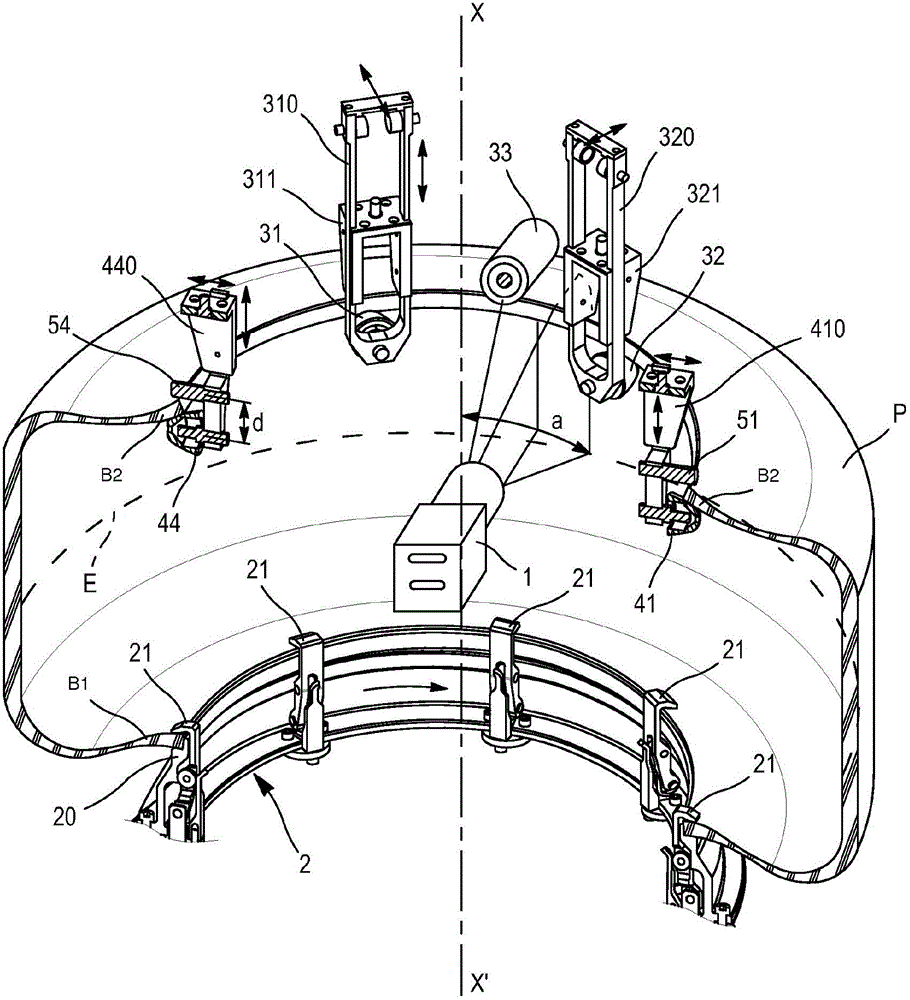
[0025] Distributed around the circumference of the rim 20 and pivoting around the pin 222 are a plurality of hooks 21 which hold the first bead B1 on the seat 25 around its entire circumference and in position. The rim 20 serves as a reference plate, itself mounted on a support ring 27 with axis XX' and connected by bearings to a frame (not shown) so that said ring 27 can pass through a motorized pinion (not shown) While rotating about the axis XX′, the motorized pinion meshes with a circular toothed rack 26 mounted on the radially outer periphery of the ring 27 . The axis of the rim is geometrically fixed r...


PUM


Abstract

The invention relates to a device for inspecting the inner surface between first and second beads of a tire (P), including means for acquiring an image of the inner surface of a tire (1), and centering means capable of locking the first bead over the entire circumference thereof on a reference plate, and driving the tire into relative rotation about the XX' axis thereof relative to said image acquisition means. The device includes means for opening and holding the second bead, which comprises two inner holding rollers (32, 32) having a substantially radial axis, and at least one outer holding roller (33) having a substantially radial axis, which are arranged substantially in the middle of the angular sector formed by the two inner holding rollers (31, 32) and are capable of bearing on the outer portion of said second bead, wherein the inner (31, 32) and outer (33) holding rollers are mounted so as to be rigidly connected in rotation relative to the axis XX' of said image acquisition means (1).

Description

technical field [0001] The present invention relates to the field of tire manufacture, and more particularly to the field of visual inspection of tires during or at the end of the production process. Background technique [0002] Tire visual inspection is very common in the tire industry and still very frequently relies on the skill of the operator responsible for detecting any visible defects on the tire surface. For this reason, a large number of auxiliary devices have been developed for the treatment and manufacture of particularly hard-to-reach visible areas such as the inner part of the tyre. [0003] As an example, as described by publication US 4 160 537, the function of these devices is to hold the beads of the tire in an open or spaced position and to set the tire into rotation. [0004] As the processing power of computing devices increases, manufacturers now foresee the possibility of automating these inspection tasks. To this end, lighting and digital imaging d...

Claims


Application Information

Patent Timeline
Patent Type & Authority Applications(China)
IPC IPC(8): G01N21/954
CPCG01N21/954G01M17/027G01M17/021H04N7/18B60C25/005B60C25/14B60C25/138B60C25/125B60C25/142
Inventor C·莱奥拜尔G·博尔
Owner MICHELIN & CO CIE GEN DES ESTAB MICHELIN
Why Eureka
Try Eureka