Ion implantation apparatus and method

A technology of ion implantation and ion beam, applied in the field of ion implantation devices, can solve problems such as difficult light capture, poor economical efficiency of photovoltaic cells, and expensive membranes

Inactive Publication Date: 2012-11-28
TWIN CREEKS TECH
View PDF6 Cites 0 Cited by
  • Summary
  • Abstract
  • Description
  • Claims
  • Application Information

AI Technical Summary

Problems solved by technology

Films made by this method can be used to form silicon-on-insulator structures, but are too costly for solar cells
Also, at thicknesses below 1 μm, the film can be so thin that efficient light

Method used


Image

  • Ion implantation apparatus and method
  • Ion implantation apparatus and method
  • Ion implantation apparatus and method

Examples


Embodiment Construction

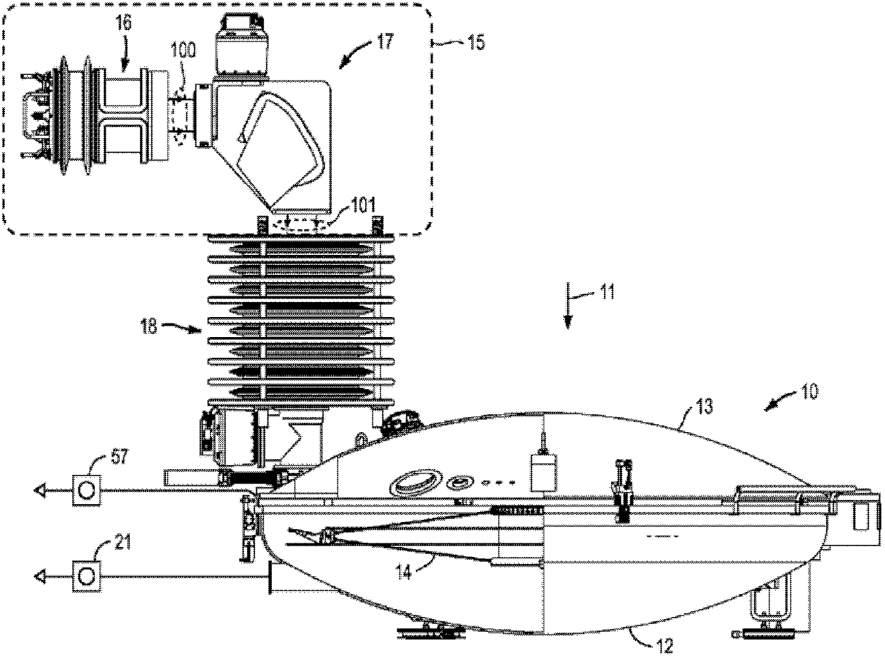
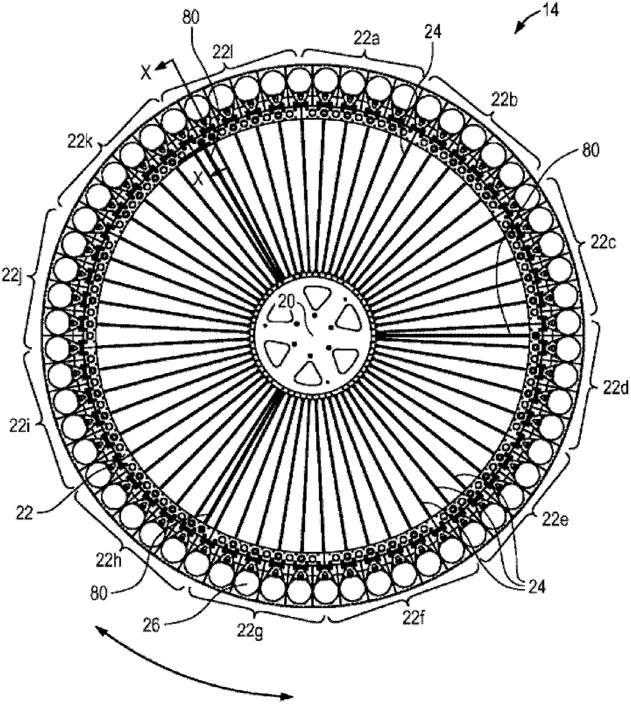
[0035] figure 1 is a schematic illustration of an implant device as an embodiment of the present invention. Ion implantation is performed in a vacuum environment, and the main operating features of the embodiments are contained within the vacuum chamber. exist figure 1 In the embodiment shown in , the vacuum chamber is shown in three interconnected sections. The first part is the processing chamber 10, when along the direction of the arrow 11 from figure 1 The processing chamber 10 has a circular outline when viewed from above. The process chamber 10 comprises a part-spherical lower wall section 12 and an opposing part-spherical upper wall section 13 forming a disc-shaped vacuum envelope thickened at the center of the disc. The processing chamber 10 contains a processing wheel 14 extending in the plane of the disc chamber 10 for rotation about a vertical axis generally aligned with the center of the disc. A substrate for processing is carried in the processing chamber 10 ...


PUM

PropertyMeasurementUnit
Lengthaaaaaaaaaa

Abstract

A hydrogen ion implanter for the exfoliation of silicon from silicon wafers uses a large scan wheel (14) carrying 50+ wafers around its periphery and rotating about an axis. In one embodiment, the axis of rotation of the wheel is fixed and a ribbon beam (101) of hydrogen ions is directed down on a peripheral edge of the wheel. The ribbon beam extends over the full radial width of wafers on the wheel. The beam is generated by an ion source (16) providing an extracted ribbon beam having at least 100mm major cross-sectional diameter. The ion source may use core-less saddle type coils (112, 112a-c) to provide a uniform field confining the plasma in the ion source. The ribbon beam may be passed through a 90-degree bending magnet (17) which bends the beam in the plane of the ribbon.

Description

[0001] related application [0002] This application is related to U.S. Patent Application No. 12 / 494,268 "Ion Implantation Apparatus and Method for Fluid Cooling" by Ryding et al., U.S. Patent Application No. 12 / 494,268 "Ion Implantation Apparatus and Method for Fluid Cooling" by Ryding et al. 12 / 494,270 "Ion Implantation Apparatus and Method," U.S. Patent Application No. 12 / 494,272 "Ion Source Assembly For an Ion Implantation Apparatus and Method of Generating Ions Therein," U.S. Patent Application No. 12 of Ryding et al. / 494,269 "Ion Implantation Apparatus," the above application incorporated herein by reference. technical field [0003] The present invention relates to ion implantation apparatus for implanting ions into planar workpieces. Particular applications of ion implantation devices include the fabrication of thin sheets of crystalline semiconductor materials such as silicon. This flake of silicon can be used to make photovoltaic cells. Background technique ...

Claims


Application Information

Patent Timeline
IPC IPC(8): H01J37/05H01J37/08H01J37/20H01J37/317F16J15/00H01J37/02
CPCH01J37/05H01J2237/057H01J2237/082H01J2237/061H01J2237/202H01J37/08H01J2237/2006H01J37/3171H01J2237/2001H01J2237/201H01J37/20H01J2237/166
Inventor G.里丁T.H.斯米克K.珀泽J.D.吉莱斯皮H.格拉维什
Owner TWIN CREEKS TECH
Why Eureka
Try Eureka