
Color ultrasonic imaging method and device

A technology of color ultrasound and imaging method, which is applied in the direction of blood flow measurement device, etc., can solve the problems affecting the visual display effect and achieve the effect of improving the visual display effect

Active Publication Date: 2012-12-05
SHENZHEN MINDRAY BIO MEDICAL ELECTRONICS CO LTD
View PDF8 Cites 11 Cited by
  • Summary
  • Abstract
  • Description
  • Claims
  • Application Information

AI Technical Summary

Problems solved by technology

At the same time, the priority estimation also enforces the distinction of blood flow signals that are not easy to distinguish, thus affecting the visual display effect

Method used


Image

  • Color ultrasonic imaging method and device
  • Color ultrasonic imaging method and device
  • Color ultrasonic imaging method and device

Examples


Embodiment Construction

[0015] The present invention will be further described in detail below through specific embodiments in conjunction with the accompanying drawings.

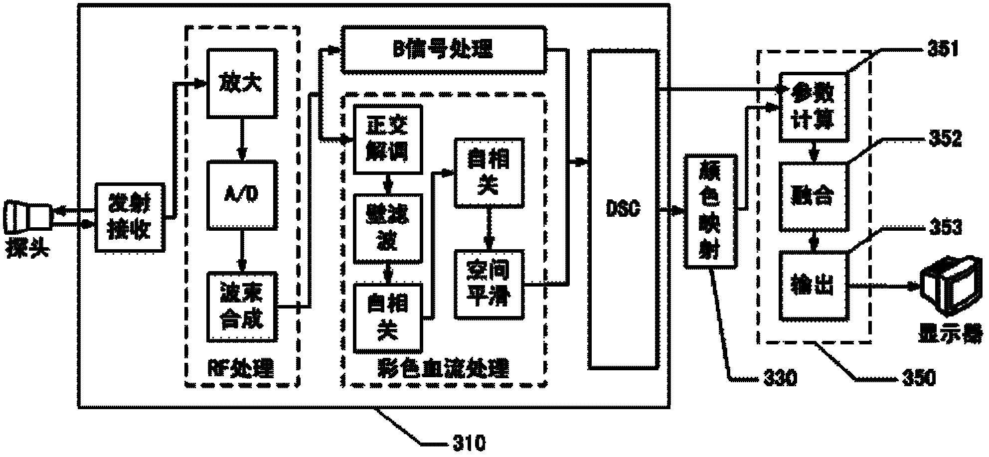
[0016] The general idea of ​​the embodiment of the present invention is: after DSC conversion, color mapping is performed, and the color image data after color mapping and the gray-scale tissue image are weighted and fused according to the strength of the blood flow signal, so that the color signal to the black and white signal is one A continuous transition, rather than a discrete judgment, greatly improves the visual display effect and makes the blood flow sensitivity have been greatly improved.

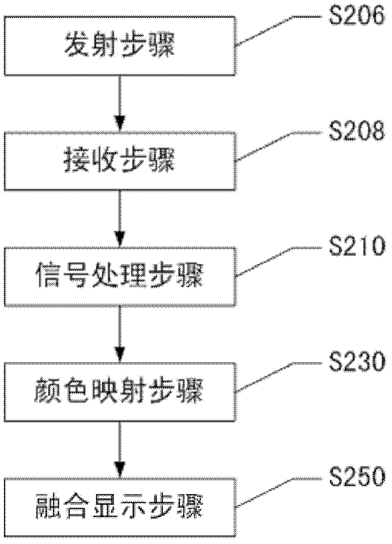
[0017] figure 2 Shows a flow chart of a color ultrasound imaging method according to an embodiment of the present invention, including: a transmitting step 206, which is used to transmit ultrasonic pulses to the target to be detected; a receiving step 208, which is used to receive the reflection of the target to be detected Ultrasoni...


PUM


Abstract

The invention discloses a color ultrasonic imaging method and device. The color ultrasonic imaging method comprises the steps as follows: an ultrasonic pulse is sent to a target to be detected; an ultrasonic echoed signal reflected by the target to be detected is received; after the ultrasonic echoed signal received is processed, tissue image data and blood flow image data are output; the blood flow image data are mapped to obtain color image data; the color image data, the tissue image data and the blood flow image data are weighted based on the intensity of a blood flow signal; and the weighted color image data is output for displaying. According to the color ultrasonic imaging method and device, as the color image data and the tissue image data are weighted based on the intensity of the blood flow signal, the color signal is continuously transited to a grayscale image, and the visual displaying effect is greatly improved.

Description

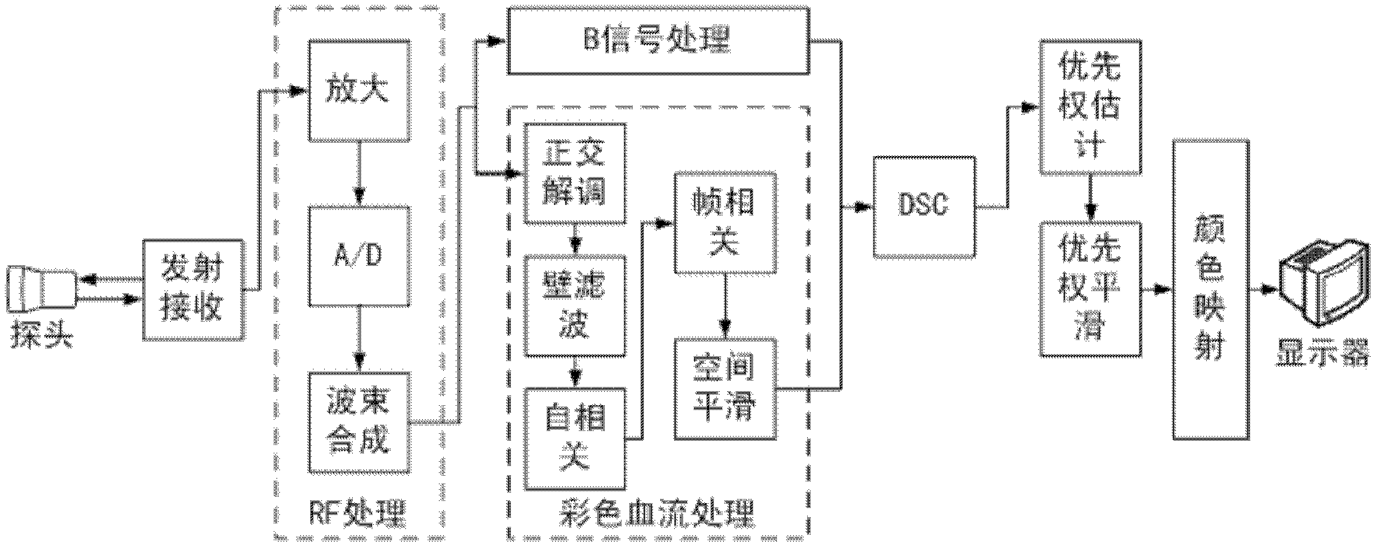
technical field [0001] The invention relates to the field of ultrasonic imaging, in particular to a color ultrasonic imaging method and a color ultrasonic imaging device. Background technique [0002] A schematic block diagram of the existing color ultrasound (ie color Doppler ultrasound) imaging system is as follows: figure 1 shown. The pulse signal sent by the probe enters the target to be detected (such as the human body), and is received by the probe after being reflected by the tissue, blood flow and moving organs of the target to be detected (such as the human body); the received signal is passed through a radio frequency (RF, Radio Frequency) ) processing circuit amplification, analog-to-digital conversion (A / D), and beam synthesis to form an RF signal; on the one hand, the RF signal forms a gray-scale image of human tissue through the B signal processing channel (also called a B image, or a black and white image), On the other hand, blood flow images (including vel...

Claims


Application Information

Patent Timeline
Patent Type & Authority Applications(China)
IPC IPC(8): A61B8/06
Inventor 邹耀贤姚斌
Owner SHENZHEN MINDRAY BIO MEDICAL ELECTRONICS CO LTD
Learn More