Wound drainage device, connection pipe fitting, connector and wound cover piece

A technology for drainage equipment and connecting pipe fittings, which is applied in the field of wound drainage equipment, connecting heads and wound coverings, and connecting pipe fittings, can solve the problems of difficulty in suctioning exudates, reduced efficiency of exudate suction, and the like. The effect of good fluid flow and efficient suction

Inactive Publication Date: 2012-12-05
SUZRIC ENTERPRISE
View PDF4 Cites 0 Cited by
  • Summary
  • Abstract
  • Description
  • Claims
  • Application Information

AI Technical Summary

Problems solved by technology

[0004] However, after the existing wound drainage device 100 has been in operation for a period of time, due to the formation of a nearly sealed state between the wound cover 110 and the wound 10, and the inter

Method used


Image

  • Wound drainage device, connection pipe fitting, connector and wound cover piece
  • Wound drainage device, connection pipe fitting, connector and wound cover piece
  • Wound drainage device, connection pipe fitting, connector and wound cover piece

Examples


no. 1 example

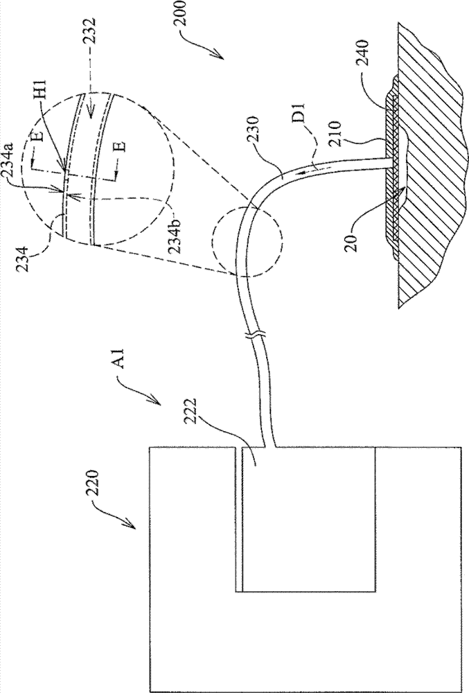
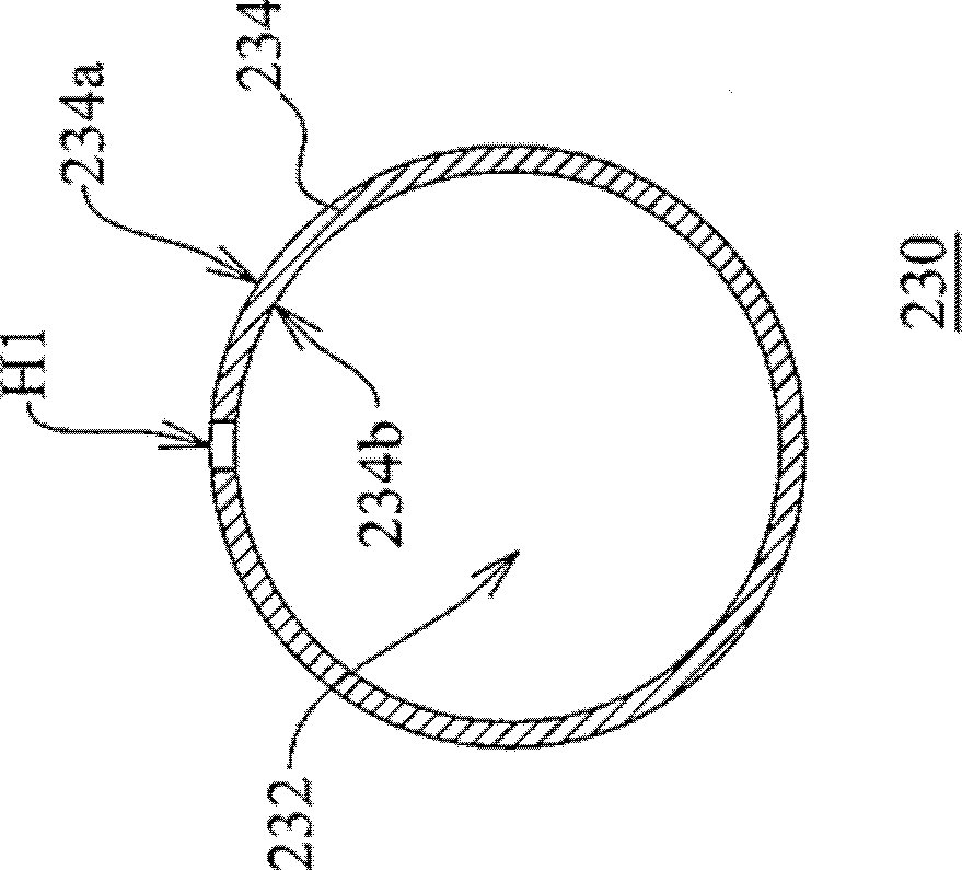
[0071] Figure 2A A schematic diagram of a wound drainage device according to the first embodiment of the present invention is shown. Figure 2B Illustrate Figure 2A A schematic cross-sectional view of the connecting pipe along the line EE. Please refer to Figure 2A versus Figure 2B The wound drainage device 200 of this embodiment is suitable for sucking exudate in a wound 20. The wound drainage device 200 includes a wound drainage assembly A1 and at least one vent H1. The wound drainage assembly A1 includes a wound cover 210, a suction device 220, a connecting tube 230 and a porous mesh 240.

[0072] The porous mesh screen 240 is suitable for being arranged on the wound 20, and the wound cover 210 is suitable for being arranged on the porous mesh screen 240 and the wound 20. In this embodiment, the porous mesh screen 240 can be made of polyurethane (PU), polyvinyl alcohol (PVA) and other foam materials (foam), which have water absorption, and the porous mesh screen 240 can a...

no. 2 example

[0078] Please refer to image 3 , Which shows an exploded schematic view of a connecting pipe according to the second embodiment of the present invention. The connecting pipe 330 of this embodiment can replace the connecting pipe 230 of the first embodiment. The connecting pipe 330 of this embodiment has a first pipe 330a, a second pipe 330b, and a connecting head 330c. The connector 330c is suitable for connecting the first tube body 330a and the second tube body 330b. The end of the first tube 330a opposite to the connecting head 330c is suitable for communicating with the wound 20 (visible Figure 2A ), and the end of the second tube 330b opposite to the connecting head 330c is suitable for being connected to the collection container 222 of the suction device 220 (visible Figure 2A ). In this embodiment, the vent hole H2 is arranged at the connector 330c.

no. 3 example

[0080] Please refer to Figure 4 , Which shows a schematic diagram of a wound drainage device according to the third embodiment of the present invention. In this embodiment, the vent hole H3 of the wound drainage device 400 is disposed on the wound cover 410 of the wound drainage assembly A3. The wound cover 410 is a cup-shaped cover. The through hole 432 of the connecting tube 430 communicates with the wound cover 410 and the collecting container 422 of the suction device 420, and further communicates with the wound 40 and the collecting container 422.


PUM


Abstract

The invention discloses a wound drainage device, a connection pipe fitting, a connector and a wound cover piece. The wound drainage device is suitable for pumping exudate in a wound. The wound drainage device comprises a wound drainage assembly and at least one vent hole. The wound drainage assembly comprises a wound cover piece and a connection pipe fitting. The wound cover piece is suitable to be allocated on the wound. The connection pipe fitting is provided with a through hole suitable for communicating wounds. The exudate in the wound is suitable to be pumped out via the through hole. The vent hole is arranged in the connection pipe fitting, and communicates the through hole with the outside environment. The wound discharge device disclosed by the embodiment of the invention is effective for pumping the exudate in the wound.

Description

Technical field [0001] The present invention relates to a drainage equipment, and in particular to a wound drainage equipment, a connecting tube, a connecting head and a wound cover applied to the wound drainage equipment. Background technique [0002] Vacuum assisted closure therapy (vacuum assisted closure therapy), or negative pressure wound therapy (negative pressure wound therapy), is a kind of auxiliary physical therapy. This treatment method uses a negative pressure pump combined with a sealing sheet or wound cover, and uses a biocompatible porous screen as a dressing. A negative pressure environment is formed in the wound. The external negative pressure reduces the volume of the porous mesh screen, which indirectly causes the wound to shrink in the middle, and the boundary cells are pulled through the porous mesh screen to promote cell division and proliferation, and accelerate wound healing. Negative pressure is transmitted through the wound through the porous mesh scr...

Claims


Application Information

Patent Timeline
IPC IPC(8): A61M27/00
Inventor 王淑芬黄成添
Owner SUZRIC ENTERPRISE
Why Eureka
Try Eureka