Carding machine

A technology of carding machine and carding element, applied in the field of carding machine, can solve problems such as limiting the speed of sliver

Active Publication Date: 2019-12-27
TRUETZSCHLER GRP SE
View PDF13 Cites 0 Cited by
  • Summary
  • Abstract
  • Description
  • Claims
  • Application Information

AI Technical Summary

Problems solved by technology

[0004] All of these have the disadvantage that the web is stretched undesirably a

Method used


Image

  • Carding machine
  • Carding machine
  • Carding machine

Examples


Embodiment Construction

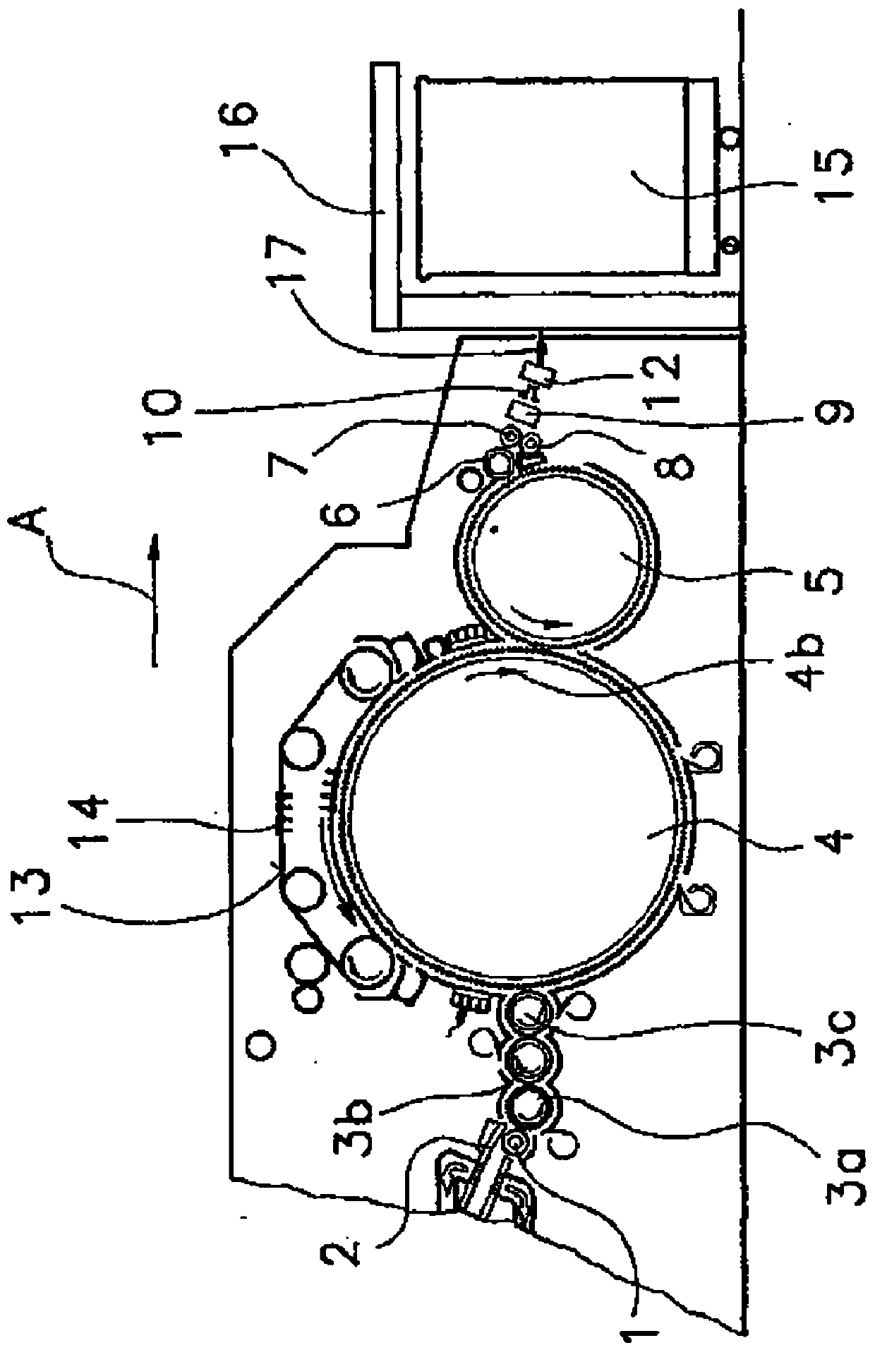
[0030] figure 1 Shown is a card according to the prior art with a feed roller 1, a feed plate 2, licker-in rollers 3a, 3b, 3c, a cylinder 4, a doffer 5, a stripping roller 6, press rollers 7, 8 , a bar separator 9, a web bell mouth 10, delivery rollers 11 (not shown) and 12, and a revolving flat 13 with a flat strip 14 that wraps around slowly. The direction of rotation of the rollers of the card is indicated by curved arrows. The direction of rotation of the cylinder is indicated by arrow 4b. At the output of the card there is a coiler 16 with a can 15 for coiling the sliver. Use A to indicate the working direction (fibrous material flow direction).

[0031] The strip separator 9 is placed behind the press rollers 7 and 8 in the working direction A. The fiber bundle is fed to the card by the feed roller 1 and the individual fibers are cleaned and aligned between the cylinder 4 and the revolving flat 13 . The formed fiber web is removed from the cylinder 4 by the doffer 5...


PUM


Abstract

The invention relates to a carding machine comprising an inlet side for fiber flocks which are supplied by the rotation of a rotating drum (4) and which are dissolved, aligned, and cleaned between stationary carding elements and circulating cover rods (14) and the drum (4) until individual fibers are formed. The resulting fiber flock (19) is transferred from the drum (4) onto a doffer (5) which isarranged upstream of at least one take-off assembly for further processing or storing the fiber flock (19). The invention is characterized in that the take-off assembly is designed as at least one conveyor belt (20, 21) which removes the fiber flock (19) directly from the doffer (5), wherein the transfer of the fiber flock (19) from the doffer (5) onto the at least one conveyor belt (20, 21) is supported by suction.

Description

technical field [0001] The invention relates to a carding machine with an infeed side for fiber bundles which are fed in by means of rolling of a rotating cylinder and between stationary carding elements and surrounding flat strips and cylinders The fiber web is disentangled into individual fibers, aligned and cleaned, and the web produced there is transferred from a cylinder to a doffer, downstream of which at least one delivery unit is arranged for further processing or storage of the web. Background technique [0002] A prior art card is described in DE10023011A1. [0003] Different delivery devices for fiber webs are known in carding machines, in which the fiber web first passes from the cylinder to the doffer, and then from the doffer further to the stripping rollers and pressure rollers, by means of It is compressed into sliver in the sliver separator and then stacked in cans. [0004] All of these have the disadvantage that the fiber web is undesirably stretched and...

Claims


Application Information

Patent Timeline
IPC IPC(8): D01G15/46
CPCD01G15/465
Inventor 阿尔明·莱德杰拉德·普菲尔德蒙尔斯
Owner TRUETZSCHLER GRP SE
Why Eureka
Try Eureka