Method and apparatus for manufacturing toner and toner manufactured by the apparatus and method

a manufacturing method and technology of toner, applied in the direction of manufacturing tools, instruments, vibration, etc., can solve the problems of degrading affecting the quality of toner, and affecting the chargeability stability of toner particles, etc., to achieve high fluidity and chargeability, high quality, and efficient and reliable manufacturing of toner over time

Active Publication Date: 2008-11-20
RICOH KK
View PDF5 Cites 38 Cited by
  • Summary
  • Abstract
  • Description
  • Claims
  • Application Information

AI Technical Summary

Benefits of technology

[0018]In view of the foregoing, exemplary embodiments of the present invention provide a method for efficiently and reliably manufacturing a toner over time, and an apparatus for manufacturing a toner using such a method. With the above-described method and apparatus, a high quality toner having high fluidity and chargeability can be stably and reliably manufactured.

Problems solved by technology

Since the polymerized toners are prepared in an aqueous medium containing a dispersant, the dispersant tends to remain on the surface of the toner particles, which degrades chargeability and stability of the toner particles, and removing the remaining dispersant requires large quantities of water.
Thus, the polymerization methods are not necessarily satisfactory.
However, the toner particles manufactured with the spray drying method are relatively coarse and large, and tend to have a larger particle diameter distribution, degrading the quality of the toner.
As a result, a number of liquid droplets discharged per unit of time is limited, decreasing productivity.
Moreover, a more complicated configuration is required to supply a gas to each discharging part.
Furthermore, when a direction of discharge of the liquid droplets and a direction of a gas flow is uncontrolled, the liquid droplets initially discharged separately from the nozzle may be combined together, especially in an area where a frequency of piezoelectric pulsation exceeds 100 kHz.
Consequently, due to such more limited vibration amplitude the nozzle may be susceptible to clogging when toner constituent liquid having a high viscosity of, for example, 10 mPa·s, in which a large amount of solid components is dispersed, is discharged from the nozzle.
Although a configuration thereof is not specifically described, the toner manufacturing apparatus disclosed in JP-A 2006-297325 provides almost the same effect as that of the method and apparatus for manufacturing a toner disclosed in JP-A 2006-293320, and therefore may be prone to the same type of problem.

Method used


Image

  • Method and apparatus for manufacturing toner and toner manufactured by the apparatus and method
  • Method and apparatus for manufacturing toner and toner manufactured by the apparatus and method
  • Method and apparatus for manufacturing toner and toner manufactured by the apparatus and method

Examples


example 1

(Preparation of Colorant Dispersion)

[0246]First, 17 parts by weight of a carbon black (REGAL® 400, from Cabot Corporation) and 3 parts by weight of a pigment dispersing agent (AJISPER PB821 from Ajinomoto Fine-Techno Co., Inc.) were added to 80 parts by weight of ethyl acetate, and primarily dispersed using a mixer having a stirring blade. The primary dispersion thus obtained was subjected to a strong shearing force using DYNO MILL to finely disperse the carbon black to prepare a secondary dispersion in which aggregates having a diameter of 5 μm or more were completely removed.

(Preparation of Wax Dispersion)

[0247]Next, 18 parts by weight of a carnauba wax and 2 parts by weight of a wax dispersing agent were added to 80 parts by weight of ethyl acetate, and primarily dispersed using a mixer having a stirring blade. The primary dispersion thus obtained was heated to 80° C. while being stirred so that the carnauba wax was melted. Thereafter, the primary dispersion was cooled down to ro...

example 2

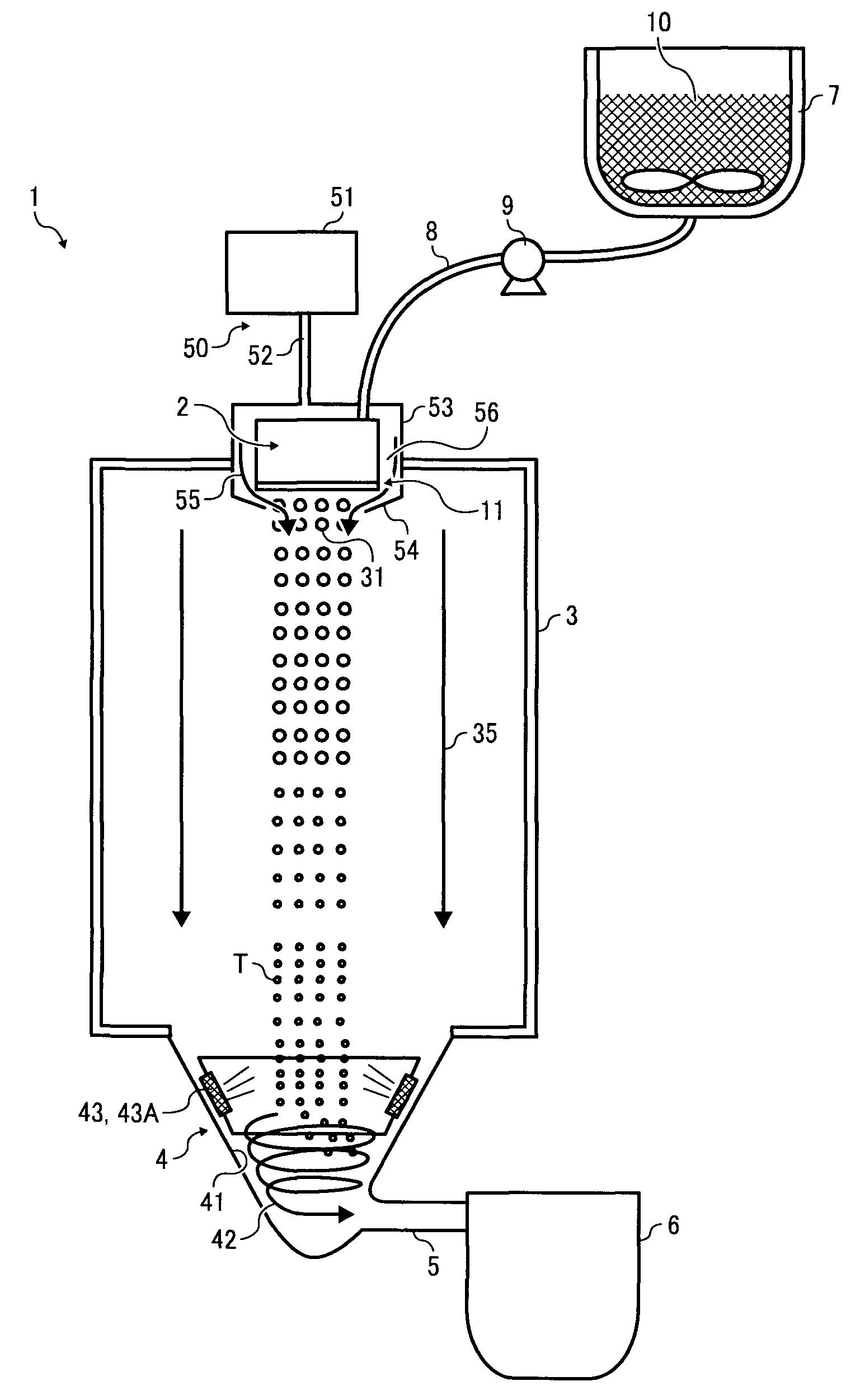
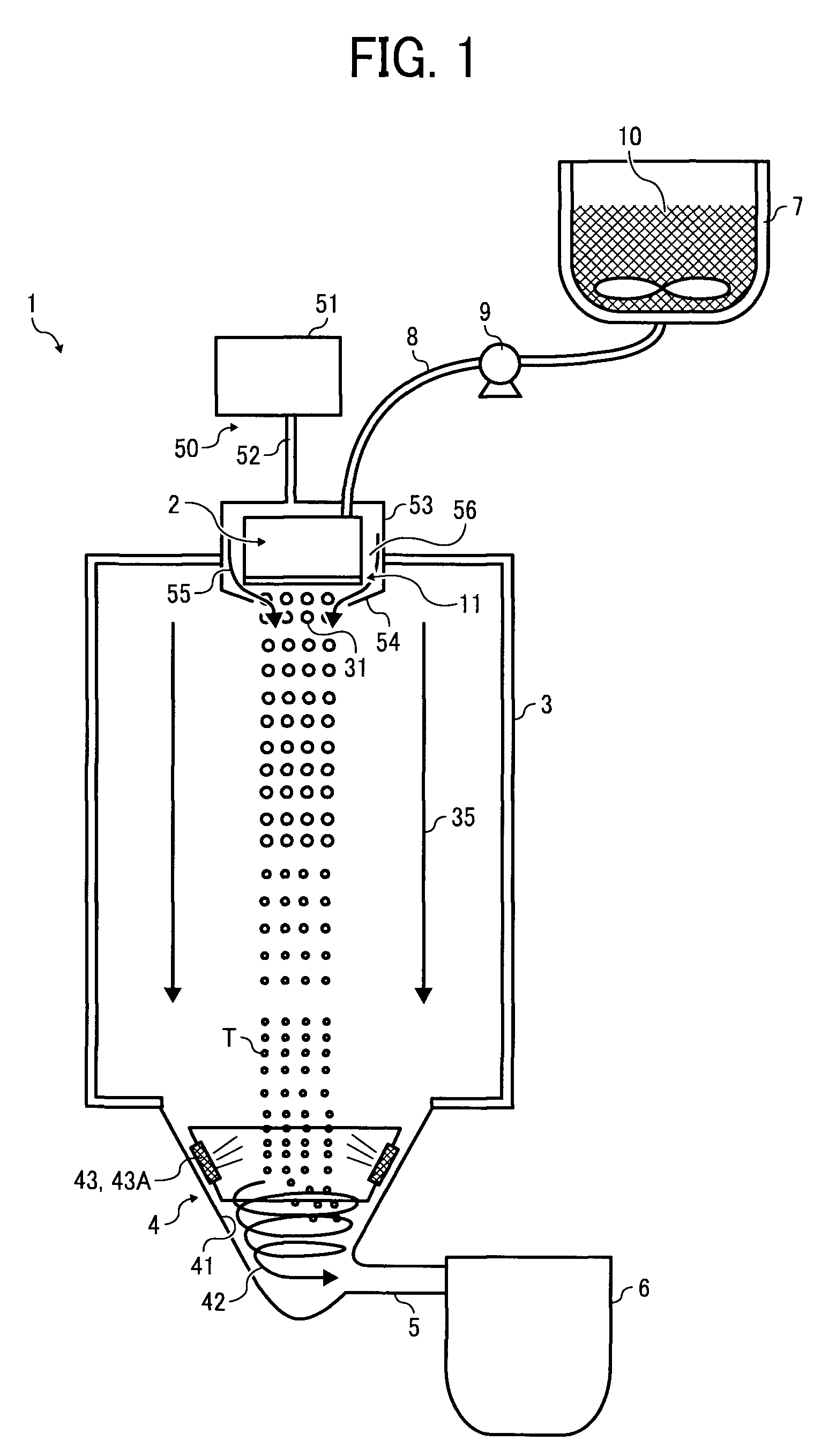
[0271]A toner was prepared in the same manner as that described in Example 1, except that gas was introduced between the gas flow path formation member 153 and the liquid droplet injection unit 102 from above through the gas leading path 157 at a pressure of 30 Kpa. As a result, toner particles having a weight average particle diameter (D4) of 5.2 μm and a number average particle diameter (Dn) of 4.9 μm were obtained. No adhesion of the toner constituent liquid 10 to the thin film 116 was observed after two-hour operation. The toner particles were evaluated in the same manner as described above, and evaluation results are shown in Table 1.

example 3

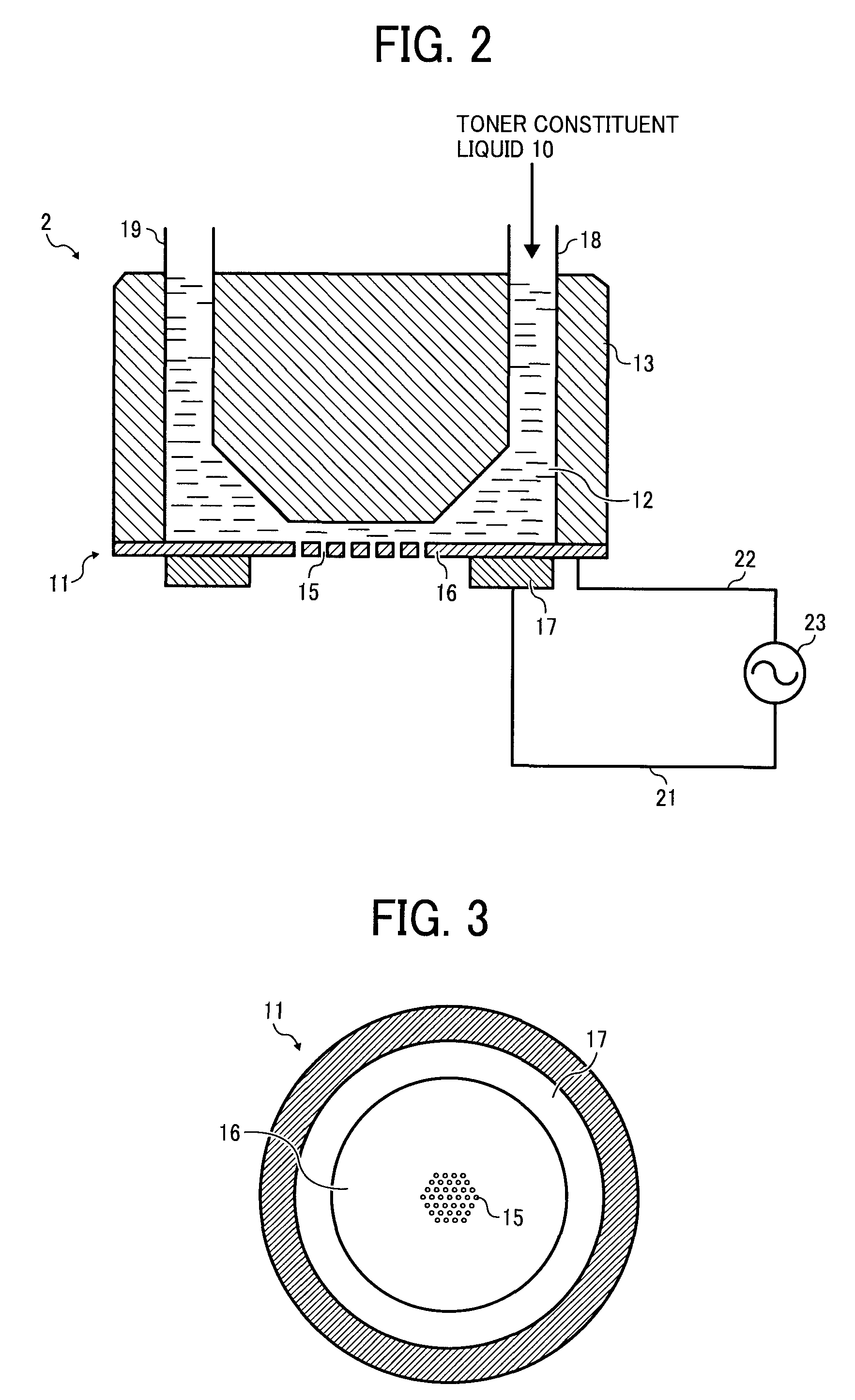
[0272]A toner was prepared in the same manner as that described in Example 1, except that the holes 115 were formed within an area having a width of 10 mm and a length of 200 mm on the thin film 116, and five liquid droplet injection units 2 each including the above-described thin film 116 were arranged in the gas flow generation means 50. As a result, toner particles having a weight average particle diameter (D4) of 5.5 μm and a number average particle diameter (Dn) of 5.0 μm were obtained. No adhesion of the toner constituent liquid 10 to the thin film 116 was observed after two-hour operation. The toner particles were evaluated in the same manner as described above, and evaluation results are shown in Table 1.


PUM

PropertyMeasurementUnit
weight average particle diameteraaaaaaaaaa
frequencyaaaaaaaaaa
viscosityaaaaaaaaaa

Abstract

A method for manufacturing a toner, including periodically forming liquid droplets of a toner constituent liquid comprising a resin and a colorant by vibrating a thin film having a plurality of holes provided on a retention part thereof to discharge the liquid droplets of the toner constituent liquid from the plurality of holes and forming toner particles by solidifying the liquid droplets discharged from the plurality of holes. In periodically forming the liquid droplets of the toner constituent liquid, a flow of gas in a direction of discharge of the liquid droplets is formed by a gas flow generation unit provided downstream from the thin film relative to the direction of discharge of the liquid droplets, including a tapered part forming an aperture corresponding to a hole formation area of the thin film.

Description

BACKGROUND[0001]1. Technical Field[0002]The present specification relates to a method and apparatus for manufacturing a toner, and a toner manufactured by the method and apparatus.[0003]2. Description of the Background[0004]In electrophotography, electrostatic recording, electrostatic printing, etc., a developer is adhered to an image bearing member such as an electrostatic latent image bearing member on which an electrostatic latent image is formed, transferred from the image bearing member onto a transfer medium such as paper, and finally fixed on the transfer medium.[0005]As the developer configured to develop the electrostatic latent image formed on the image bearing member, a two-component developer, which includes a carrier and a toner, and a one-component developer consisting essentially of a toner (e.g., magnetic toner and non-magnetic toner) are known.[0006]As a dry toner for use in electrophotography, electrostatic recording, electrostatic printing, etc., a pulverized tone...

Claims


Application Information

Patent Timeline
Patent Type & Authority Applications(United States)
IPC IPC(8): G03G9/10B28B17/00
CPCB01J2/04B01J2/18G03G9/0804G03G9/0815B29B9/12B29B9/10B29B2009/125
Inventor NORIKANE, YOSHIHIROOHTANI, SHINJIWATANABE, YOHICHIROHSUZUKI, KAZUMI
Owner RICOH KK
Why Eureka
Try Eureka