Double clapboard flow distribution device for thin-strip continuous casting

A clapboard and continuous casting technology, which is applied in the field of thin strip continuous casting double-baffle flow distribution devices, can solve the problems of large fluctuations, multiple structures, and no turbulent effect of the flow distributor, and achieve saving refractory materials, stable and uniform The effect of flow distribution and process saving

Active Publication Date: 2014-12-24
BAOSHAN IRON & STEEL CO LTD
View PDF5 Cites 0 Cited by
  • Summary
  • Abstract
  • Description
  • Claims
  • Application Information

AI Technical Summary

Problems solved by technology

[0009] 1. There are many structures, which increase the additional transportation link of the equipment;
[0010] 2. The increase of the intermediate transition package will increase the difficulty of its installation, and it needs to be equipped with another mechanism during take-off and landing;
[0011] 3. Since the molten steel falls directly into the flow distributor below through the narrow gap, the fluctuation inside the flow distributor caused by the excessive drop is also relatively large, and there is no effect of smoothing the turbulence;
[0017] 3. Whether the porous refractory plate can pass the molten steel properly still needs to be verified
The advantages of this structure are: simple form and low cost; the disadvantage is: it is difficult to control the fluctuation and uniformity of solidification

Method used


Image

  • Double clapboard flow distribution device for thin-strip continuous casting
  • Double clapboard flow distribution device for thin-strip continuous casting
  • Double clapboard flow distribution device for thin-strip continuous casting

Examples


Embodiment Construction

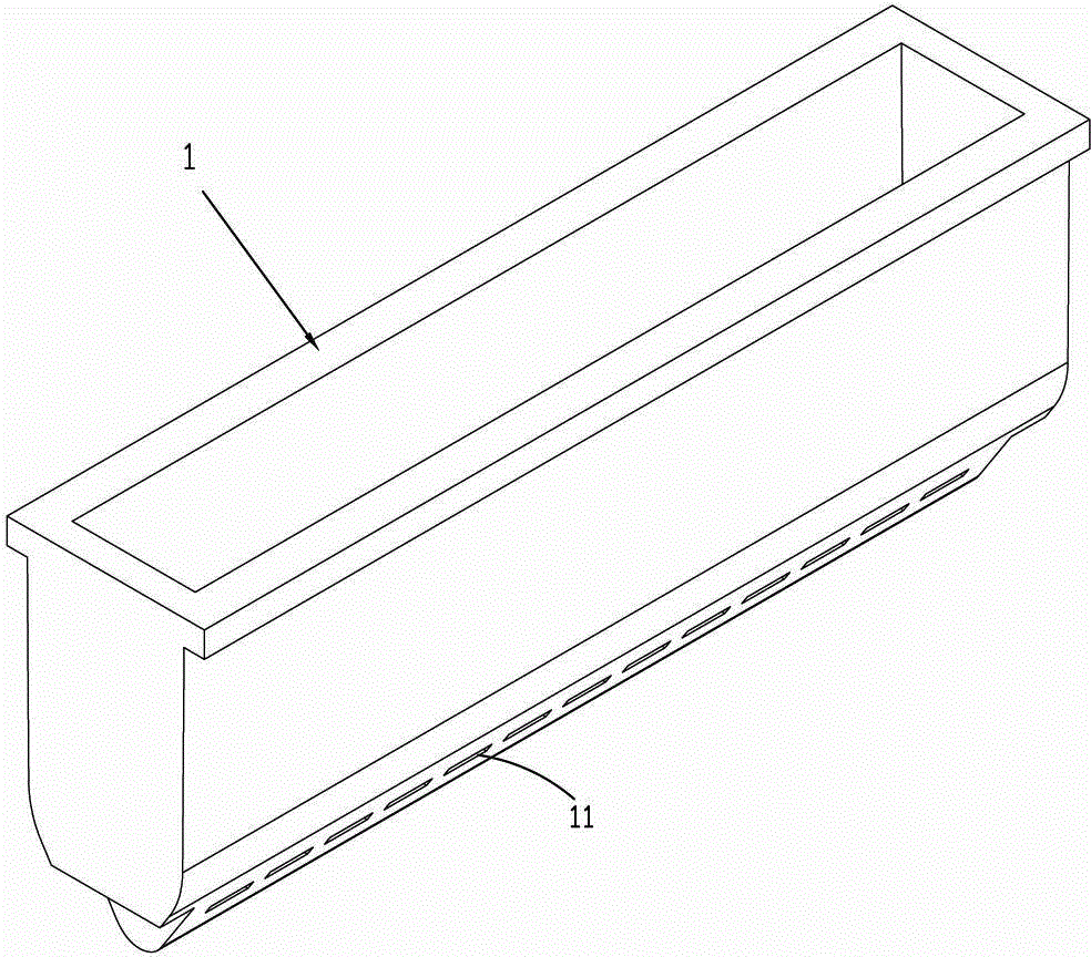
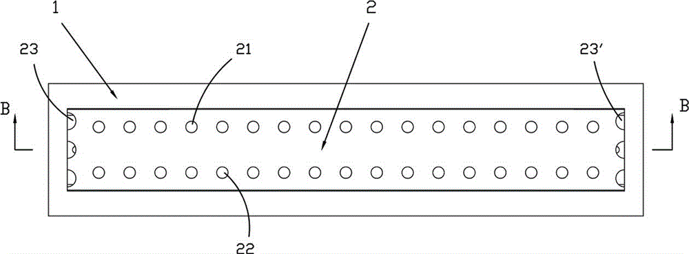
[0042] see Figure 1 to Figure 6 , a thin strip continuous casting double partition flow distribution device of the present invention, which includes a flow distributor body 1, first and second partitions 2,3.

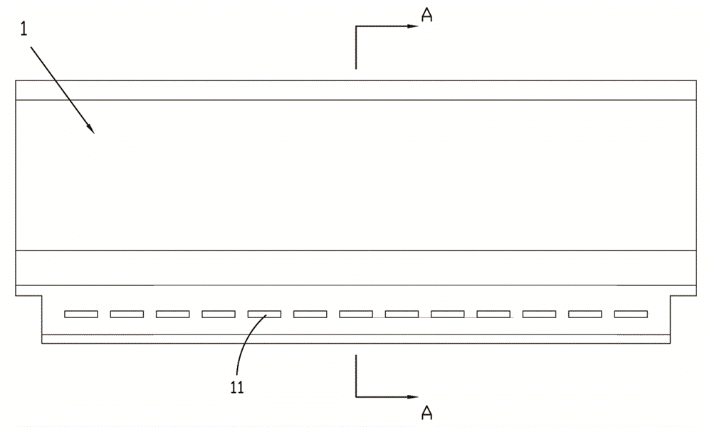
[0043] Distributor body 1, which is a box structure with an upper end opening, the lower part of the side walls at both ends is arranged in a stepped shape, and the bottom of the body is a pointed pyramid structure; the two side walls of the lower part of the body are provided with a number of spit holes 11 at intervals along the length direction .

[0044] The first and second partitions 2 and 3 are arranged up and down in the middle and lower parts of the flow distributor body 1 respectively, and divide the cavity of the flow distributor body 1 into upper, middle and lower chambers, and the upper chamber 101 is used for eliminating turbulence The middle chamber 102 is a confluence area, and the lower chamber 103 is a turbulence suppression chamber; the first partiti...


PUM


Abstract

The invention relates to a double clapboard flow distribution device for thin-strip continuous casting. The double clapboard flow distribution device comprises a flow distributor body, a first clapboard and a second clapboard, wherein the flow distributor body has a box body structure of which the upper end is provided with an opening, lower parts of side walls at two ends are arranged in a step type, and the bottom of the body has a closed-angle conical structure; two side walls of the lower part of the body are provided with a plurality of discharge holes at intervals along the length direction; the first clapboard and the second clapboard are arranged on the middle part and the lower part in the distributor body up and down respectively, so that a cavity of the distributor body is divided into an upper cavity, a middle cavity and a lower cavity; the first clapboard is provided with two rows of steel passing holes; the cross section of the second clapboard is in an inverted T shape; steel accommodating chambers are formed on two sides of the lower side of the first clapboard of the cavity of the distributor body respectively and consist of the first clapboard, the second clapboard, vertical clapboards and the side walls of two ends of the distributor body; side steel passing holes are formed on two sides of the first clapboard corresponding to the steel accommodating chambers respectively; and edge discharge holes which face side closing plates are formed at the bottoms of the steel accommodating chambers. By the double clapboard flow distribution device, molten steel which flows into a flow distributor from a water gap can be buffered, and the tapping amount of the discharge holes and the flow speed of the molten steel can be reduced effectively.

Description

technical field [0001] The invention relates to the field of twin-roll thin strip continuous casting, in particular to a thin strip continuous casting double partition flow distribution device. Background technique [0002] Twin-roll strip continuous casting is a growth process in which two casting rolls rotating in opposite directions are used as crystallizers to directly produce liquid metal into thin strip steel with a thickness of less than 10mm. Compared with the traditional thin strip production process, this technology has the advantages of shortening the process flow, saving energy, reducing production costs and improving the mechanical properties of the strip. [0003] The thin strip continuous casting process is a casting and rolling process that is both related and different from traditional continuous casting. The main process is to inject molten steel into the tundish, distribute the molten steel into the flow distributor through the nozzle, and then inject the...

Claims


Application Information

Patent Timeline
Patent Type & Authority Patents(China)
IPC IPC(8): B22D11/06B22D11/103
Inventor 任三兵樊俊飞方园
Owner BAOSHAN IRON & STEEL CO LTD
Why Eureka
Try Eureka