Total-column translation machine of motor train unit
A technology for EMUs and trains, which is applied in the direction of turntable/moving platform, railway car body parts, transportation and packaging, etc. It can solve the problems of small turning radius, energy waste, and increased difficulty of train diversion and rectification, etc., and achieves benefits Adjust rail materials to facilitate the effect of inter-node rectification
- Summary
- Abstract
- Description
- Claims
- Application Information
AI Technical Summary
Problems solved by technology
Method used
Image

Examples
Embodiment Construction
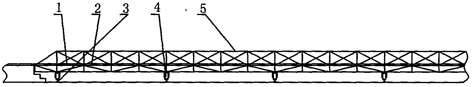
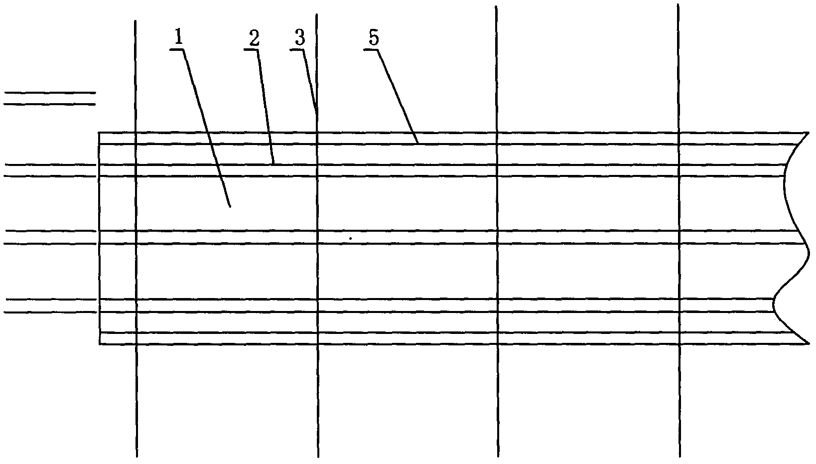
[0020] The full-train translation machine of the EMU in the present invention is composed of a cap and its platform 1, a train track 2, a cap running track 3, a cap wheel 4, a power unit, a control device, and a foundation.
[0021] The cap frame 5 of the present invention is a steel structure, the train track 2 is laid on the cap platform 1, a plurality of sets of wheels 4 are arranged under the cap, and a multi-channel cap wheel running track 3 is laid on the foundation, and a railway track at both ends of the cap There is a linkage control room on the side, and the main body of the power device and the control device is set under the platform at the end of the bearing platform. In order to facilitate the observation of the working status of the locking device and the parking situation of the train, the control room is semi-submerged, that is, the control room is nearly half lower than the bearing platform. Countertop 1
[0022] The platform running track 3 is arranged verti...
PUM
 Abstract
Description
Claims
Application Information