Rubber wheel driven high speed train and line

A technology for high-speed trains and rubber wheels, which is applied in the field of trains and vehicles, can solve the problems of increasing the radius of the curve, increasing the cost and loss of the line, and reducing the safety, so as to reduce the radius of the curve, reduce the cost of the line, and reduce noise pollution. Effect

Inactive Publication Date: 2007-08-01
李孝龙
View PDF0 Cites 12 Cited by
  • Summary
  • Abstract
  • Description
  • Claims
  • Application Information

AI Technical Summary

Problems solved by technology

[0002] Due to the low adhesion between the wheels and rails in the current rail transit, the weight of the locomotive has to be greatly increased to obtain higher adhesion; but the excessive self-weight also increases the line cost and loss accordingly, and due to the If the friction

Method used


Image

  • Rubber wheel driven high speed train and line
  • Rubber wheel driven high speed train and line

Examples


Embodiment 1

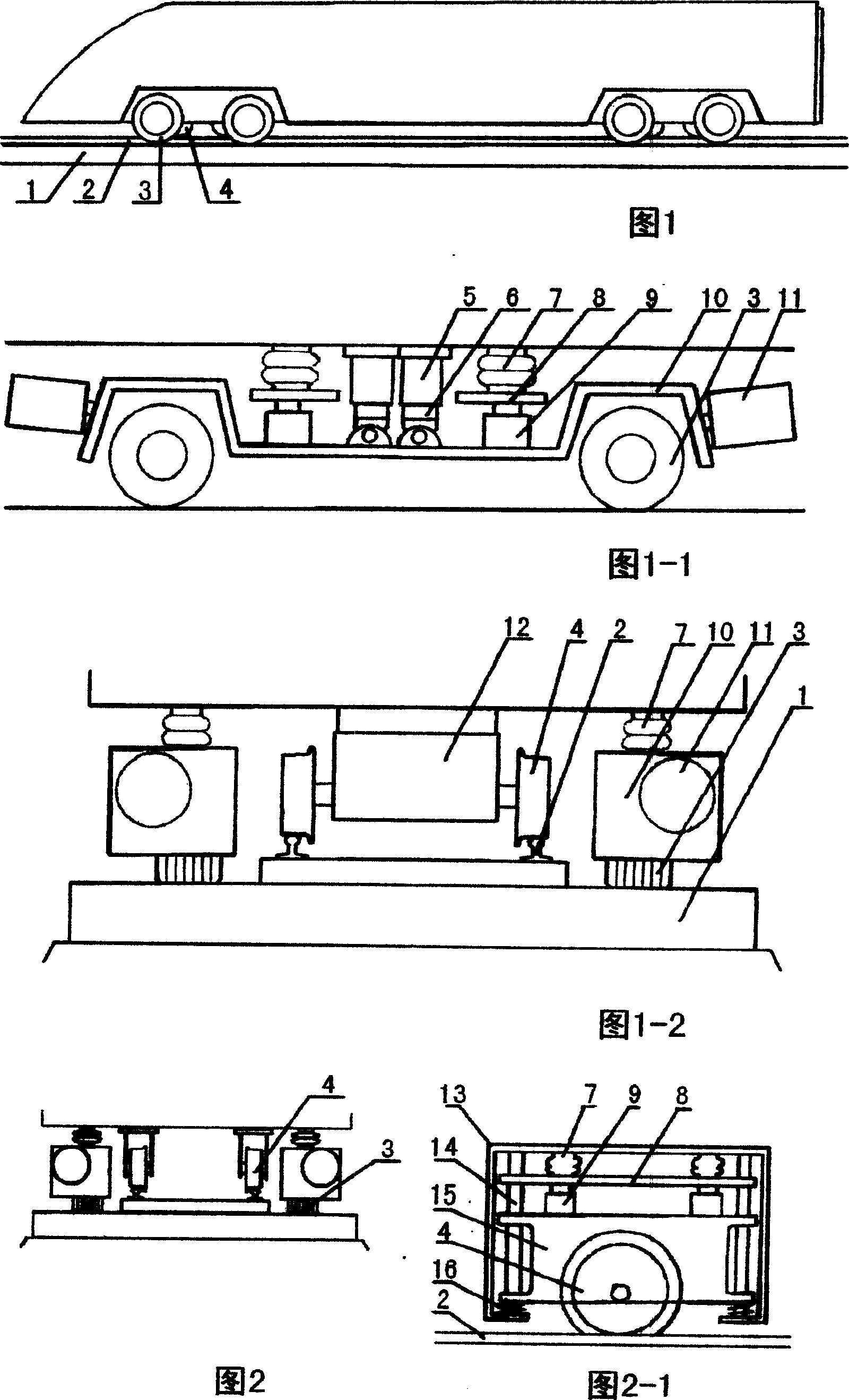
[0020] As shown in Fig. 1, the train with rubber driving wheels 3 installed under the vehicle runs on the line where the road surface 1 is laid on both sides of the rail 2, the steel wheels 4 run on the rails, and the rubber driving wheels 3 run on the road on both sides of the rails Drive the vehicle forward.

[0021] As shown in Fig. 1-1, the wheel frame 10 equipped with the rubber drive wheel 3 is installed under the two sides of the train in a non-rotatable manner through the rocker 6 and the rod sleeve 5. Shock air spring 7 and hydraulic cylinder 9, while rubber drive wheel 3 is driven by motor 11. In application, increase the pressure of the hydraulic cylinder 9, and the hydraulic cylinder presses the train upward through its upper support plate 8 and the air spring, thereby increasing the weight of the train carried by the rubber driving wheel 3, thereby increasing the driving friction pressure between the rubber driving wheel and the road surface . When the pressure ...

Embodiment 2

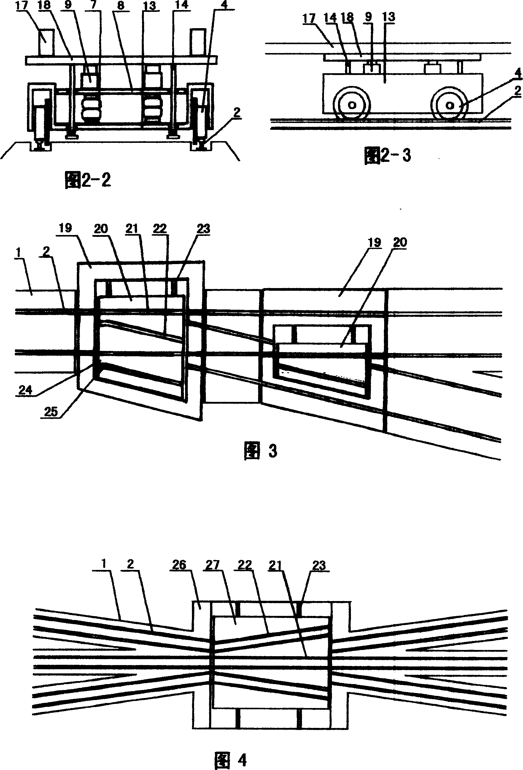
[0030] As shown in Fig. 3, two turnout sleepers 19 in the line are a group of translational turnouts, the straight rail and the branch rail on the ram 20, and the straight transition rail 21 and the branch transition rail 22 are provided with rubber wheels to pass through. The notch interval is 24. The translational turnout utilizes the ram 20 that can move laterally in the chute of the turnout sleeper 19, and the straight transition rail 21 and the fork transition rail 22 on the ram and the road surface for rubber wheels to move laterally in the straight line and the branch line, thereby realizing Switching of straight and branch roads. In the application, the ram 20 in the chute of the two turnout sleepers 19 in the line is simultaneously moved by the electric device through the screw rod or the hydraulic device to complete the line conversion. Since there are notches between adjacent straight rails and branch rails or straight transition rails and branch transition rails i...


PUM


Abstract

The present invention provides railway which two steel rail sides are paved road surface, ate the same time and the train vehicle running on the railway which is equipped with steel wheel and rubber driving wheel. The steel wheel runs on the steel rail and the rubber driving wheel runs on the two road surfaces of steel rail two sides. The vehicle is guided by the steel wheel and driven by the rubber driving wheel, the both carry the vehicle weight and runs on railway. Due to using rubber wheel driving, the strong driving friction between rubber driving wheel and road surface is far larger than the driving friction (adhesion force) between the wheels and the rail of prior high speed train, so the train speed is far higher than the prior various high speed trains. The train can obtain out side superelevation on curve road through adjusting the pressure adjusting (lifting) device on the rubber driving wheel and the steel wheel of train two sides. The advantages of the invention are: the train has excellent starting, accelerating, climbing and braking performance, the carve road radius is small; the noise pollution between wheel and rail is reduced substantially. And it can decrease corner radius and the road cost.

Description

technical field [0001] The invention relates to a line on which road surfaces are laid on two sides of steel rails, and a train vehicle which is equipped with steel wheels and rubber driving wheels to run on the line. Background technique [0002] Due to the low adhesion between the wheels and rails in the current rail transit, the weight of the locomotive has to be greatly increased to obtain higher adhesion; but the excessive self-weight also increases the line cost and loss accordingly, and due to the If the friction force is too small, the radius of the curve will increase, the braking distance of the vehicle will increase, and the safety will decrease. When used as urban rail transit, the noise pollution between the wheel and rail is relatively large. Contents of the invention [0003] The invention provides a line with paved roads on both sides of the steel rail, and a train vehicle equipped with steel wheels and rubber driving wheels at the same time. The vehicle i...

Claims


Application Information

Patent Timeline
IPC IPC(8): B60F1/00B61B1/00B61F13/00
Inventor 李孝龙
Owner 李孝龙
Why Eureka
Try Eureka