Guide wheel rail vehicle and rail

A technology for rail vehicles and guide wheels, applied in the field of rail transportation, can solve the problems of complex composition and structure of turnouts, large turning radius, etc.

Inactive Publication Date: 2019-03-05
张启明
View PDF0 Cites 13 Cited by
  • Summary
  • Abstract
  • Description
  • Claims
  • Application Information

AI Technical Summary

Problems solved by technology

[0011] The technical problem to be solved by the present invention is that the turning radius of the current rail vehicles is large and the line switching method is based on the action of the turnout (mainly the active action), while the composition and structu

Method used


Image

  • Guide wheel rail vehicle and rail
  • Guide wheel rail vehicle and rail
  • Guide wheel rail vehicle and rail

Examples


no. 1 Embodiment

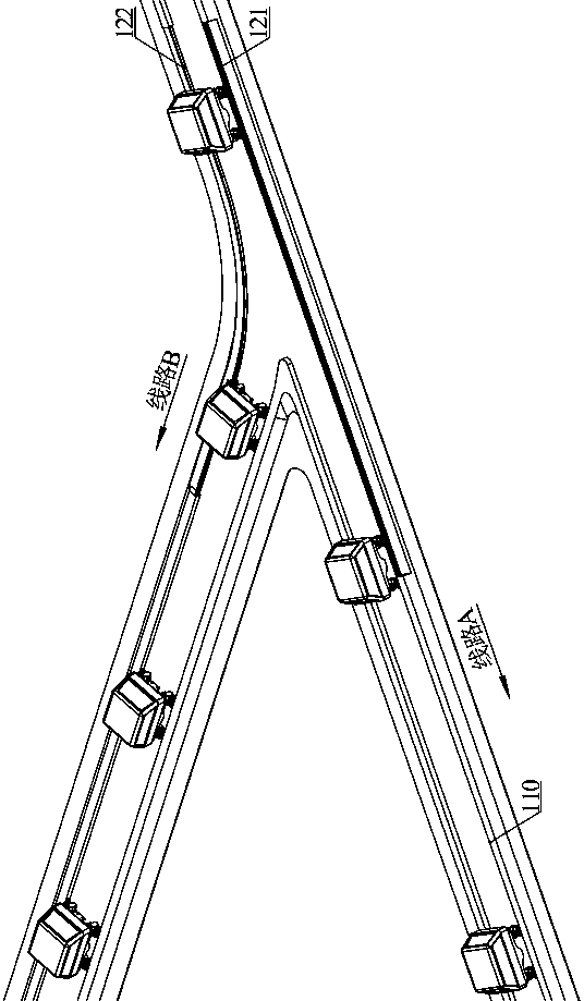
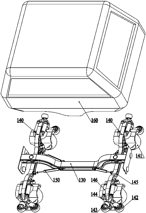
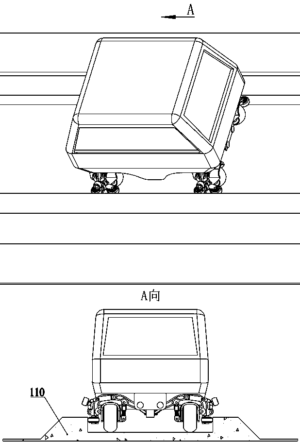
[0047] figure 1 A scenario in which this embodiment is used is shown. In this embodiment, the running devices of the vehicle are all distributed in the lower part of the vehicle, which are two sets of guide wheel running device assemblies that have both guiding and driving capabilities and are integrated with a guiding regulation mechanism—the axle 140. The two sets of axles pass through It is hinged with the vehicle frame 130 to realize structural integration. The detailed structure of the whole vehicle structure and the axle is as follows: figure 2 As shown, the carriage 160 is installed on the vehicle frame 130, and the vehicle axle 140 is hinged with the vehicle frame 130 in the middle of itself, and also has a steering auxiliary cylinder 150 to stabilize the direction.

[0048] The driving wheel 141 is fixedly connected with the axle beam 145 (excluding shock absorption); the guide wheel 142 is fixedly installed on both sides of the vehicle frame beam 145 . The guide ...

no. 2 Embodiment

[0059] Figure 5 A scenario in which this embodiment is used is shown. In this embodiment, the running gear of the vehicle is distributed on the top and bottom of the vehicle, including two sets of guide wheel running gear assemblies 240 and two sets of guiding control devices 250, and all components of the running gear are structurally integrated through the vehicle frame 230 .

[0060] The detailed structure and composition of the driving device are as follows: Image 6 , Figure 7 As shown, the four guide wheels 242 on the upper part of the guide wheel walking device assembly 240 realize the steering control of the driving wheel 241 through the rotating shaft 243 (integral fixed connection form); the guide control device 250 includes a pressing wheel 251 (the specific function of the guide wheel Positioning), wheel shaft 252, telescopic arm 253, control oil cylinder 254, wheel shaft locking pin 255, telescopic arm locking element 256, etc., under the actuation of control...

no. 3 Embodiment

[0066] Figure 11 A scenario in which this embodiment is used is shown. In this embodiment, the running devices of the vehicle are all distributed at the bottom of the vehicle, and the principle of bridge steering is applied, which are two sets of guide wheel running device assemblies 340 with the same structure and symmetrically installed. The two sets of assemblies are structurally integrated by being hinged with the frame 350, and four steering auxiliary cylinders 360 are used to control the driving stability of the vehicle and to control the driving direction of the vehicle on road sections without guide rails. The compartment 370 is fixedly connected to the vehicle frame 350 .

[0067] The structure of the guide wheel walking device is as follows: Figure 13 As shown, the vehicle is carried and driven by the road wheels 342 when driving; two guide wheels 345 are arranged under the middle part of the integral axle 341 to control the direction of travel of the vehicle alo...


PUM


Abstract

A guide wheel rail vehicle and a rail comprise the guide wheel rail vehicle, a rail structure and a line switching method, wherein the guide wheel rail vehicle is mutually formed by a guide wheel running device, a guide regulation and control device, a vehicle body and the like, wherein the guide wheel running device is used for guiding an advancing direction of the vehicle; the guide regulation and control device is used for regulating and controlling different wheel and rail matching schemes; the vehicle body is arranged for specific function positioning; and the rail structure and the lineswitching method are adaptive to vehicle characteristics. The guide wheel rail vehicle and the rail have at least two matching schemes; in the operation process, by switching the different matching schemes, lines of the vehicle can be switched in the case that all rail components do not act; and each running device of the vehicle has a specific hinging relation with each other so that the vehiclecan sheer off on the rail with small curvature radius. According to the guide wheel rail vehicle and the rail, problems that the turning radius of an existing rail vehicle is large and the steering depends on sequential action of a rail turnout are solved; and the guide wheel rail vehicle and the rail are applied to the field of related rail traffic, such as material conveying and resident trips.

Description

technical field [0001] The invention relates to the field of rail transportation, in particular to a guide wheel rail vehicle and a corresponding track and line switching method. Background technique [0002] In the field of modern transportation and logistics, rail transit is an important application form. It has the advantages of fixed lines, simple driving operation, and low energy consumption. It has been widely used in many fields of production and life in modern society. In urban transportation, light rail, subway, tram, railcar, monorail and other rail transportation tools provide great convenience for residents to travel; in long-distance transportation, trains and EMUs running on the railway network provide The production and life of the national economy provide a large amount of passenger and freight capacity; on the factory production line and in the mine roadway, rail flat cars and suspended monorail transport vehicles are common tools for factory mineral flow. ...

Claims


Application Information

Patent Timeline
IPC IPC(8): B61F13/00E01B25/28
CPCB61F13/00E01B25/28
Inventor 张启明
Owner 张启明
Why Eureka
Try Eureka