
Vehicle dynamic weighing system

A vehicle and load cell technology, applied in the field of weighing, can solve the problems of vehicle weight error, weighing result deviation, weight deviation, etc., and achieve the effect of improving weighing deviation, reducing weighing deviation, and reducing deviation.

Active Publication Date: 2012-09-19
SICHUAN XINGDA MINKO ELECTR MECHANICAL ENG
View PDF5 Cites 13 Cited by
  • Summary
  • Abstract
  • Description
  • Claims
  • Application Information

AI Technical Summary

Problems solved by technology

If the driver in order to steal the toll, it is very likely that the speed will be reduced to a very small speed when passing the quartz sensor, and the wheel will speed up after passing the quartz sensor, which will cause serious deviations in the weighing results
[0006] And when using the above-mentioned dynamic scale to weigh the vehicle, if you want to get more accurate data, there are two requirements for the passing vehicle, one is to move at a uniform speed, and the other is to fix the center of gravity, otherwise the measured vehicle weight will have a large error
However, in the actual application process, it is impossible for most road vehicles to meet these two conditions at the same time. For example, for a vehicle filled with liquid, the center of gravity will also shake left and right when the liquid is bumped from side to side. Very big
[0007] Therefore, the single-row quartz sensor cannot solve the weighing deviation caused by the slow passing of the vehicle or the unstable center of gravity.
Moreover, the weighing result of the quartz sensor is affected by the unevenness of the road, and the weighing result will also deviate from the actual vehicle weight.

Method used


Image

  • Vehicle dynamic weighing system
  • Vehicle dynamic weighing system
  • Vehicle dynamic weighing system

Examples


Embodiment Construction

[0026] The following will clearly and completely describe the technical solutions in the embodiments of the present invention with reference to the accompanying drawings in the embodiments of the present invention. Obviously, the described embodiments are only some, not all, embodiments of the present invention. Based on the embodiments of the present invention, all other embodiments obtained by persons of ordinary skill in the art without creative efforts fall within the protection scope of the present invention.

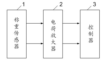
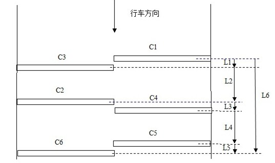
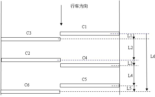
[0027] see figure 1 , is a schematic structural diagram of a vehicle dynamic weighing system in an embodiment of the present invention. The vehicle dynamic weighing system of the present invention includes a load cell 1, a charge amplifier 2 and a controller 3. The load cell 1 includes at least Three rows of quartz sensors, the waveform signal generated by the load cell 1 when the wheel is rolling, is amplified by the charge amplifier 2 and transmitted to the contr...


PUM


Abstract

The invention discloses a vehicle dynamic weighing system comprising a weighing sensor, a charge amplifier and a controller. The weighing sensor comprises at least three rows of quartz sensors paved on a lane; and each row of quartz sensors comprise two quartz piezoelectric sensors which are respectively and transversely arranged on a left half lane and a right half lane. When a vehicle passes bythe weighing sensor, each wheel runs over multiple quartz piezoelectric sensors, each quartz piezoelectric sensor generates a wave-form signal which is transmitted to the controller; and after abnormal waveform signals are removed by the controller, the axle weight of each of the rest waveform signals is calculated, a final axle weight is obtained after averaging is carried out, then the final axle weights of all wheels are added, and therefore the final vehicle weighing value can be obtained. By adoption of the paving mode of three or more rows of quartz sensors, weighing deviation caused bypavement irregularity or vehicle vibration can be effectively reduced; and especially, the vehicle dynamic weighing system has a better effect for traveling vehicles with the center of gravity being unsteady.

Description

technical field [0001] The invention relates to the weighing field, in particular to a vehicle dynamic weighing system. Background technique [0002] The dynamic weighing of existing vehicles generally uses a single row of quartz sensors to cover the lane. The quartz sensors detect the pressure and speed of each axle of the vehicle passing on the road surface, and then use an embedded computer to calculate the weight of each axle and the overall weight of the vehicle. gross vehicle weight. Its calculation formula is: [0003] Axle weight = axle speed / sensor width * piezoelectric waveform integral area * correction factor [0004] The total weight of the vehicle = the sum of the axle loads [0005] It can be seen from the above formula that when the speed of the vehicle passing the quartz sensor is low, the axle weight measured by the quartz sensor will be very small, and there will be a very large deviation between the final vehicle weight and the actual vehicle weight....

Claims


Application Information

Patent Timeline
IPC IPC(8): G01G19/03G01G23/01
Inventor 陈朝利汪威吕建春
Owner SICHUAN XINGDA MINKO ELECTR MECHANICAL ENG
Learn More