Cooling fan

A heat dissipation fan and fan wheel technology, applied to parts of pumping devices for elastic fluids, non-variable pumps, pump devices, etc., can solve problems such as inconvenience and lack of suitable structures for general products, and avoid blockage Effect

Inactive Publication Date: 2012-12-05
ADDA
View PDF7 Cites 3 Cited by
  • Summary
  • Abstract
  • Description
  • Claims
  • Application Information

AI Technical Summary

Problems solved by technology

[0002] see Figure 19 and Figure 20 , a conventional cooling fan 10 includes a base plate 11, a ring wall 12, a stator 13, a circuit board 14, a fan wheel 15 and a cover plate 16, the base plate 11 has a first air inlet 11a , the ring wall 12 has an air outlet 12a, the ring wall 12 is arranged on the bottom plate 11 to define a receiving groove 17, the stator 13, the circuit board 14 and the fan wheel 15 are arranged in the receiving groove 17 , and the circuit board 14 is electrically connected to the stator 13 to drive the fan wheel 15 to rotate counterclockwise, the cover plate 16 has a second air inlet 16a, and the cover plate 16 is combined on the ring wall 12, when the When the fan wheel 15 rotates counterclockwise, the air outside the cooling fan 10 is sucked into the housing groove 17 through the first air inlet 11a and the second air inlet 16a, and is pushed out through the air outlet 12a. The air outside the cooling fan 10 will be accompanied by dust of different materials due to different environments, so when the dust is sucked into the housing groove 17, the dust will adhere to the fan wheel 15 and the fan wheel 15 in the housing groove 17. The stator 13, the circuit board 14, the inner wall of the ring wall 12, the periphery of the first air inlet 11a and the periphery of the second air inlet 16a, when the fan wheel 15 rotates, the accumulated dust over the years will cause wind resistance, making the The fan wheel 15 rotates slowly, thereby reducing the cooling performance, or causing the cooling fan 10 to be damaged and unusable
[0003] This shows that above-mentioned existing cooling fan obviously still has inconvenience and defect in structure and use, and urgently needs to be further improved
In order to solve the above-mentioned problems, the relevant manufacturers have tried their best to find a solution, but for a long time no suitable design has been developed, and the general product has no suitable structure to solve the above-mentioned problems. This is obviously the relevant industry. Urgent problem

Method used


Image

  • Cooling fan
  • Cooling fan
  • Cooling fan

Examples


Embodiment Construction

[0096] In order to further explain the technical means and effects of the present invention to achieve the intended purpose of the invention, the specific implementation, structure, characteristics and effects of the cooling fan proposed according to the present invention will be described in detail below in conjunction with the accompanying drawings and preferred embodiments. The description is as follows.

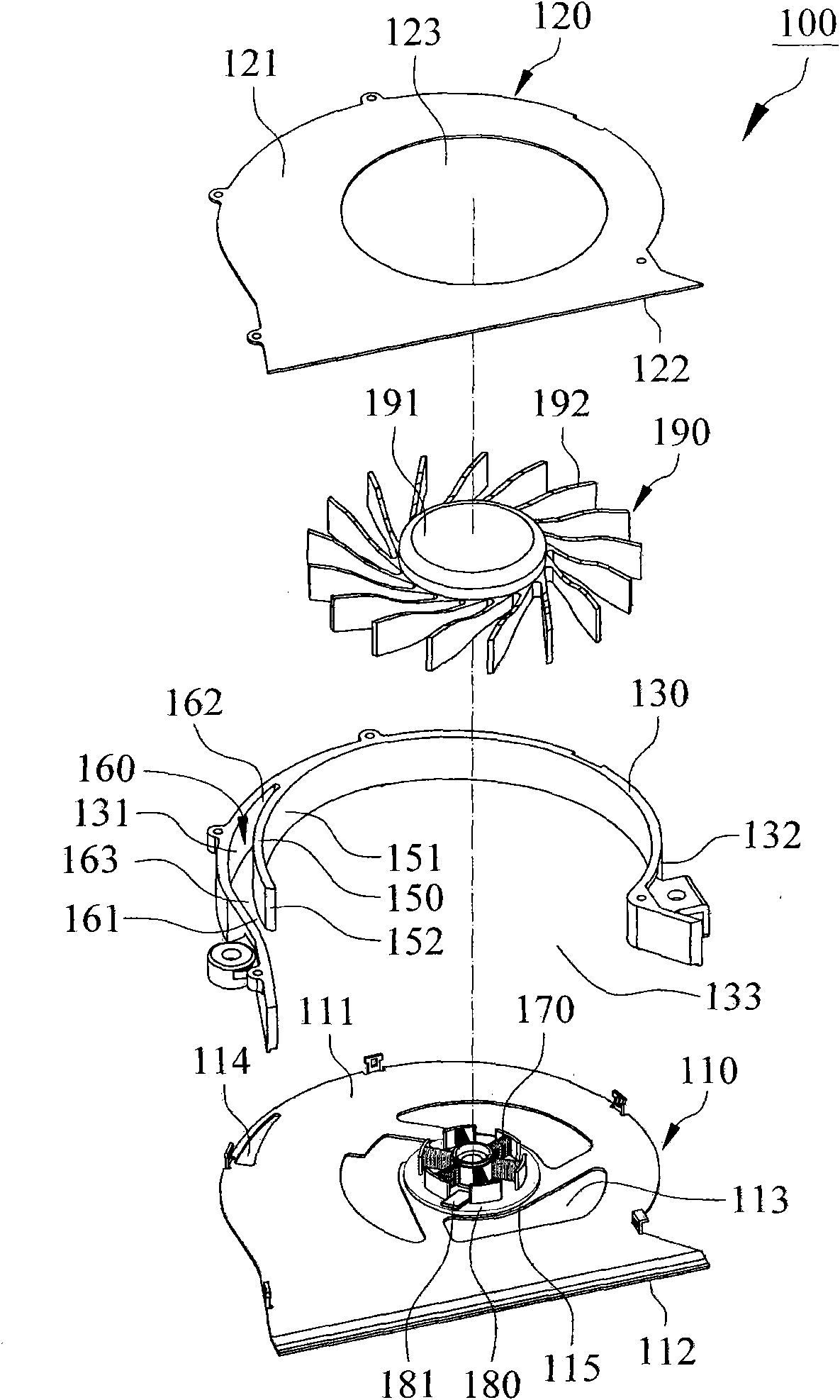
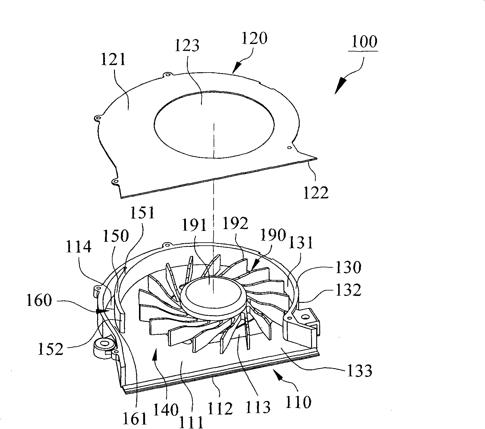
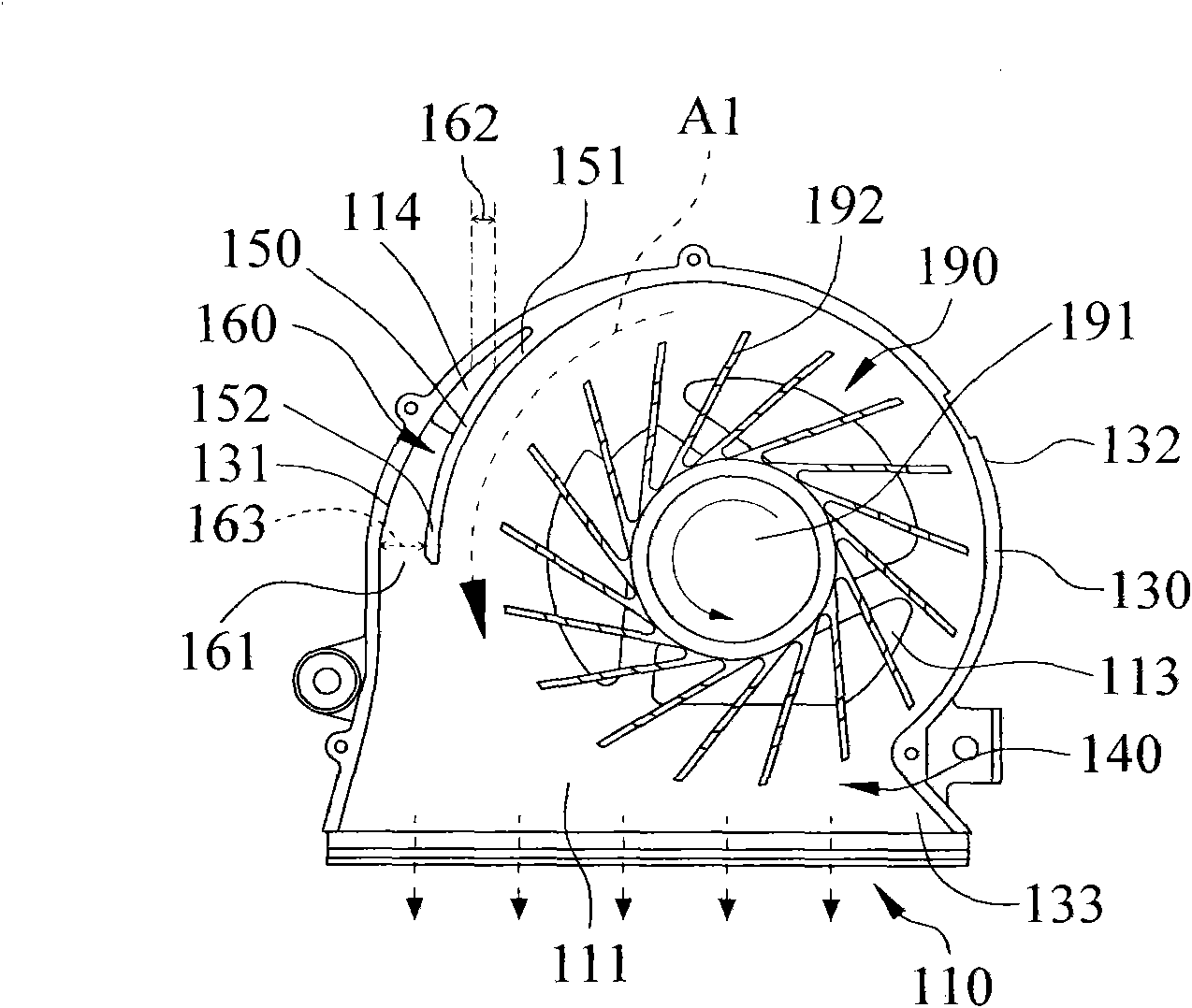
[0097] see Figure 1 to Figure 4 , which is the first embodiment of the present invention, a cooling fan 100 which includes a first board 110, a second board 120, a ring wall 130, a spacer rib 150, a stator 170, a circuit board 180 And a fan wheel 190, the first plate body 110 has a first upper surface 111, a first lower surface 112, a first opening 113 passing through the first upper surface 111 and the first lower surface 112, and A dust outlet 114 that runs through the first upper surface 111 and the first lower surface 112, please refer to figure 1 , in this embodi...


PUM


Abstract

The invention relates to a cooling fan, comprising a first board, a second board, a ring wall, a spacing rib, a stator and a vane. The first board is provided with a row of dust ports, the first board, the second board and the ring wall define a holding space, in which the spacing rib is equipped, and a row of air channels are formed between the spacing rib and the ring wall, an opening is formed between one end of the spacing rib and the ring wall, the air channels are connected through the row of dust ports, the opening is connected to the air channels and the holding space, and the air stream formed by the rotation of the vane driven by the stator mobilizes the dust remained in the holding space to be exhausted through the opening, the air channels and the dust ports.

Description

technical field [0001] The invention relates to a heat dissipation fan, in particular to a heat dissipation fan which discharges the dust in the accommodating space of the heat dissipation fan. Background technique [0002] see Figure 19 and Figure 20 , a conventional cooling fan 10 includes a base plate 11, a ring wall 12, a stator 13, a circuit board 14, a fan wheel 15 and a cover plate 16, the base plate 11 has a first air inlet 11a , the ring wall 12 has an air outlet 12a, the ring wall 12 is arranged on the bottom plate 11 to define a receiving groove 17, the stator 13, the circuit board 14 and the fan wheel 15 are arranged in the receiving groove 17 , and the circuit board 14 is electrically connected to the stator 13 to drive the fan wheel 15 to rotate counterclockwise, the cover plate 16 has a second air inlet 16a, and the cover plate 16 is combined on the ring wall 12, when the When the fan wheel 15 rotates counterclockwise, the air outside the cooling fan 10 is...

Claims


Application Information

Patent Timeline
IPC IPC(8): F04D25/08F04D29/42
Inventor 周政春陈昱丞苏彦民
Owner ADDA
Why Eureka
Try Eureka