Supercharge Your Innovation With Domain-Expert AI Agents!

Refrigeration cycle device

A circulation device and expansion device technology, applied in the direction of fluid circulation arrangements, gas circulation refrigerators, irreversible circulation compressors, etc., can solve the problems of reduced construction, etc., to achieve the effect of reducing connection construction and saving installation space

Active Publication Date: 2014-11-19
MITSUBISHI ELECTRIC CORP
View PDF4 Cites 0 Cited by
  • Summary
  • Abstract
  • Description
  • Claims
  • Application Information

AI Technical Summary

Problems solved by technology

In addition, since the heat medium piping connecting each refrigeration cycle apparatus of the refrigeration cycle apparatus described in Patent Document 1 is arranged outside the refrigeration cycle apparatus, the man-hours for the connection construction of the heat medium pipes at the installation site are not greatly reduced, and there are still Desire to reduce construction issues

Method used


Image

  • Refrigeration cycle device
  • Refrigeration cycle device
  • Refrigeration cycle device

Examples


Embodiment approach 1

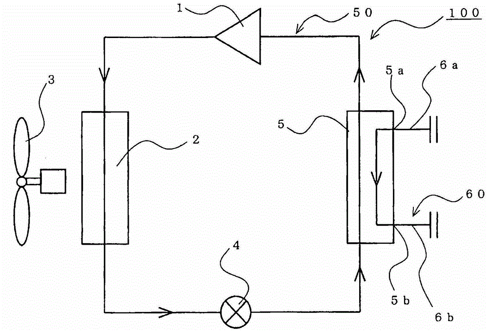
[0023] figure 1 It is a piping configuration diagram showing an example of the refrigeration cycle apparatus according to Embodiment 1 of the present invention.

[0024] Such as figure 1 As shown, the refrigeration cycle apparatus 100 of the first embodiment includes a refrigerant circuit 50 and a heat medium circuit 60.

[0025] The refrigerant circuit 50 circulates the refrigerant inside. The compressor 1, the condenser 2, the expansion valve 4, and the evaporator 5 are sequentially connected by refrigerant pipes to form the refrigerant circuit 50. The expansion valve 4 is an expansion device. In addition, in the refrigerant circuit 50 of the first embodiment, one of the condenser 2 and the evaporator 5 is a heat medium heat exchanger that exchanges heat between the refrigerant and the refrigerant flowing in the heat medium circuit 60. In addition, the other of the condenser 2 and the evaporator 5 is an air heat exchanger that exchanges heat between the refrigerant and air.

[0...

Embodiment approach 2

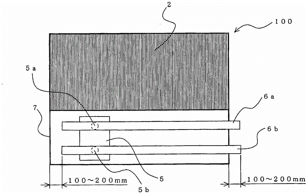
[0040] In the first embodiment, only one end of the heat medium inlet pipe 6 a and the heat medium outlet pipe 6 b is arranged in the housing 7. The present invention is not limited to this, and both ends of the heat medium inlet pipe 6 a and the heat medium outlet pipe 6 b may be provided in the housing 7. In addition, in the second embodiment, parts that are not specifically described are the same as those in the first embodiment, and the same functions and configurations as those in the first embodiment are described using the same reference numerals as in the first embodiment.

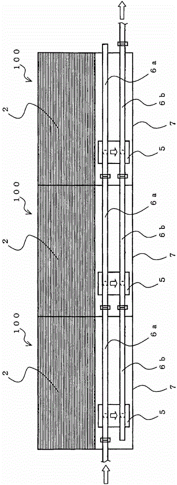
[0041] Figure 4 It is a longitudinal cross-sectional schematic diagram which shows an example of the refrigeration cycle apparatus of Embodiment 2 of this invention.

[0042] Such as Figure 4 As shown, in the refrigeration cycle apparatus 100 of the second embodiment, both ends of the heat medium inlet pipe 6a and the heat medium outlet pipe 6b as the connection ports are separated from the side surfa...

Embodiment approach 3

[0051] In the first and second embodiments, the refrigeration cycle device 100 in which the heat medium heat exchanger is used in the condenser or the evaporator is described, but the present invention can also be implemented in both the condenser and the evaporator. The refrigeration cycle device of the heat medium heat exchanger. In addition, in the third embodiment, parts that are not specifically described are the same as those in the first embodiment, and the same functions and configurations as those in the first embodiment will be described using the same reference numerals as in the first embodiment.

[0052] Image 6 It is a piping configuration diagram showing an example of a refrigeration cycle apparatus according to Embodiment 3 of the present invention.

[0053] Such as Image 6 As shown, the refrigeration cycle apparatus 100 of the third embodiment is provided with a condenser 8 as a heat medium heat exchanger instead of the condenser 2 as an air heat exchanger shown ...


PUM


Abstract

The invention provides a refrigeration cycle device, and when a plurality of such refrigeration cycle devices are installed in connection, connecting construction of thermal medium piping which is conducted at the installation site can be reduced (reduction of working hours of construction) and installation space can be saved. An evaporator of the refrigeration cycle device (100) is a thermal medium heat exchanger which enables a refrigerant and a thermal medium to exchange heat, and the refrigeration cycle device has thermal medium inlet piping (6a) whose midway part is connected with a thermal medium inlet (5a) of the evaporator (5), one end part of at least one part being arranged inside a housing (7); and a thermal medium outlet piping (6b) whose midway part is connected with a thermal medium outlet (5b) of the evaporator (5), one end part of at least one part being arranged inside the housing (7). When the plurality of such refrigeration cycle device (100) is being connected, end parts of thermal medium inlet piping (6a) and end parts of thermal medium outlet piping (6a) are connected in any housing (7) of these refrigeration cycle device (100).

Description

Technical field [0001] The present invention relates to a refrigeration cycle device for cooling or heating a heat medium such as water and brine, and in particular to a refrigeration cycle device connected with other refrigeration cycle devices. Background technique [0002] Conventionally, there has been known a refrigeration cycle device that heats or cools the heat medium using a heat medium heat exchanger that exchanges heat between a refrigerant and a heat medium (water, brine, etc.) between the condenser and evaporator of the refrigerant circuit. In this type of refrigeration cycle device, when it is necessary to heat or cool a heat medium exceeding the capacity of one refrigeration cycle device, multiple refrigeration cycle devices may be installed so that each heat medium heat exchanger is connected to the heat medium pipe. Connect to collect the heat medium heated or cooled by each refrigeration cycle device in the heat medium pipe. [0003] When a plurality of refrigera...

Claims


Application Information

Patent Timeline
Patent Type & Authority Patents(China)
IPC IPC(8): F25B41/00
CPCF25B2309/1414F25B2500/17F25B2400/077F25B2500/05F25B41/40F25B1/00
Inventor 伊藤拓也大越靖石田和之大塚修七种哲二
Owner MITSUBISHI ELECTRIC CORP
Features
  • R&D
  • Intellectual Property
  • Life Sciences
  • Materials
  • Tech Scout
  • Unparalleled Data Quality
  • Higher Quality Content
  • 60% Fewer Hallucinations
Learn More