Centrifugal casting equipment

A technology of centrifugal casting and mold, which is applied in the field of centrifugal casting devices, can solve the problems of increasing installation space of centrifugal casting devices, expansion of equipment installation space, and increase of equipment costs, so as to achieve high-efficiency centrifugal casting operations, effective use of space, and reduction of equipment costs Effect

Inactive Publication Date: 2005-01-19
HONDA MOTOR CO LTD
View PDF1 Cites 8 Cited by
  • Summary
  • Abstract
  • Description
  • Claims
  • Application Information

AI Technical Summary

Problems solved by technology

Since the pipe drawing device is long in size corresponding to the axial length of the rotary mold 1, the installation space of the centrifugal casting device as a whole increases, resulting in poor space efficiency.
[0011] In addition, in the above-mentioned conventional technology, in order to efficiently perform the centrifugal casting operation, two or more rotating molds 1 are arranged side by side. In this case, it is necessary to install a washing device 10 on each rotating mold 1. , injection device 11, pouring mechanism 9 and pipe drawing device
In this way, the installation space of the equipment will be greatly enlarged and the cost of the equipment will be greatly increased.

Method used


Image

  • Centrifugal casting equipment
  • Centrifugal casting equipment
  • Centrifugal casting equipment

Examples


Embodiment Construction

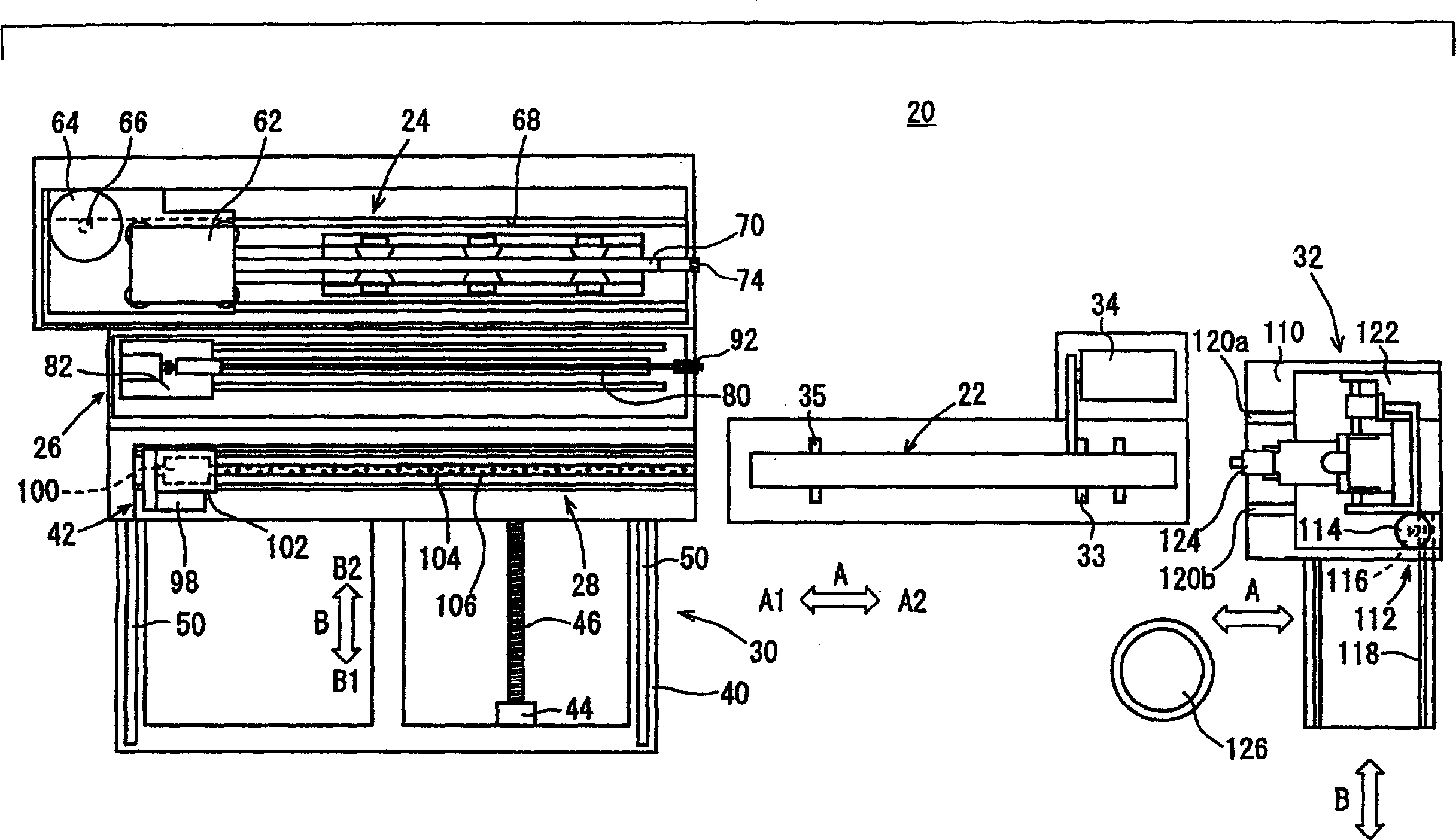
[0043] figure 1 It is a schematic plan view of the centrifugal casting device 20 according to the first embodiment of the present invention.

[0044]The centrifugal casting device 20 includes: a cylindrical centrifugal casting mold 22; a workpiece pulling mechanism 24 arranged side by side (direction of arrow A1) in the axial direction (direction of arrow A) of the above-mentioned centrifugal casting mold 22; Mechanism 26 and coating material application mechanism 28; Make the above-mentioned workpiece pulling mechanism 24, the above-mentioned cleaning mechanism 26 and the above-mentioned coating material application mechanism 28 along the direction of arrow B intersecting with the above-mentioned axial direction (direction of arrow A) A unit drive mechanism 30 for overall movement; and a pouring mechanism 32 disposed on the other side in the axial direction of the centrifugal casting mold 22 (direction of arrow A2).

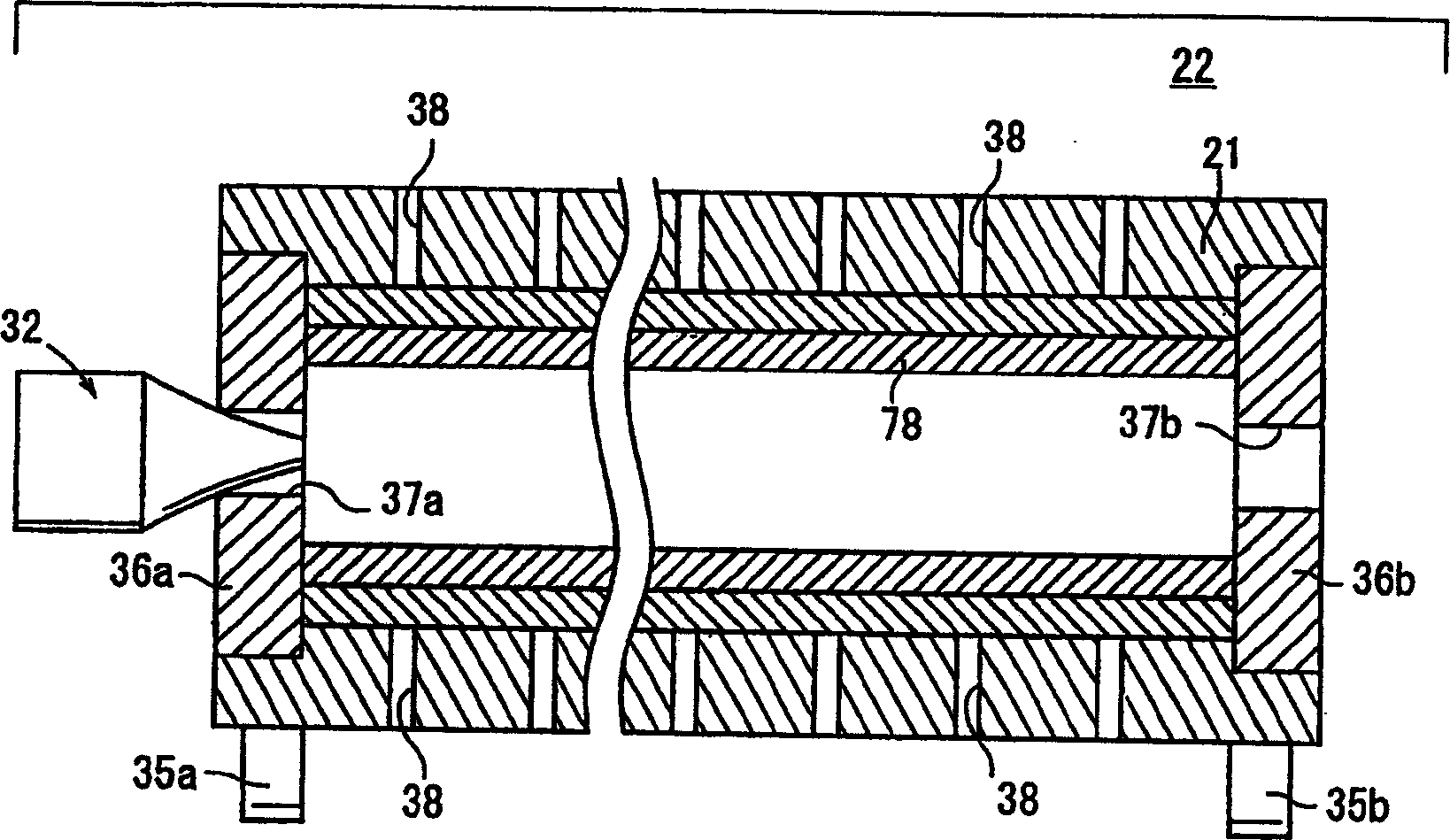
[0045] The centrifugal casting mold 22 has a long hollow...


PUM


Abstract

A centrifugal casting equipment, comprising a work extraction mechanism (24), a cleaning mechanism (26), and a facing coating mechanism (28) disposed parallel with each other on one side of a centrifugal casting metal mold (22), a unit drive mechanism (30) for integrally moving the work extraction mechanism (24), cleaning mechanism (26), and facing coating mechanism (28) in the direction of arrow (B) crossing the direction of arrow (A), and a molten metal filling mechanism (32) disposed on the other side of the centrifugal casting metal mold (22).

Description

technical field [0001] The present invention relates to a centrifugal casting device for casting a pipe through a centrifugal casting mold while automatically drawing said pipe. Background technique [0002] A cylindrical hollow mold is rotated at high speed around its axis, and the injected molten metal is attached to the inner wall surface of the mold by centrifugal force, thereby manufacturing a hollow cast pipe. Such centrifugal casting methods are well known. [0003] As a centrifugal casting apparatus used in such a centrifugal casting method, an apparatus disclosed in Japanese Patent Application Laid-Open No. Sho 57-94461 is known. The device as Figure 20 As shown, a front and rear moving guide rail 2 is arranged on one side of the rotary mold 1 in the axial direction, and a pipe drawing device not shown in the figure is arranged on the other side of the rotary mold 1 in the axial direction. [0004] A forward and backward moving platform 3 is arranged on the forwa...

Claims


Application Information

Patent Timeline
Patent Type & Authority Applications(China)
IPC IPC(8): B22D13/02B22D13/10
CPCB22D13/108B22D13/102B22D13/107B22D13/023
Inventor 佐藤秀司内藤司郎平井文男小玉春喜甲斐升克畑中节美宫尾升佐佐木武
Owner HONDA MOTOR CO LTD
Why Eureka
Try Eureka