
Vehicle dynamic weighing system

A dynamic weighing system and vehicle technology, applied in the field of weighing, can solve the problems that abnormal situations cannot be handled well and weighing results are inaccurate, so as to achieve accurate weighing results and reduce weighing deviations

Active Publication Date: 2013-08-28
SICHUAN XINGDA MINKO ELECTR MECHANICAL ENG
View PDF8 Cites 0 Cited by
  • Summary
  • Abstract
  • Description
  • Claims
  • Application Information

AI Technical Summary

Problems solved by technology

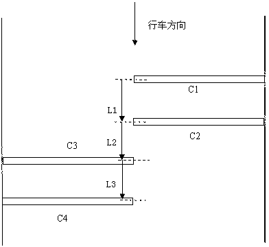
[0006] The purpose of the present invention is to provide a dynamic weighing system for vehicles, which solves the problem that the existing single-row quartz weighing system cannot handle abnormal conditions well, resulting in inaccurate weighing results, and provides a dynamic weighing system for vehicles. Four quartz sensors are laid in parallel and staggered on the toll lane, which can effectively deal with the abnormal situation when the vehicle passes the sensor road section, and accurately measure the vehicle weight

Method used


Image

  • Vehicle dynamic weighing system
  • Vehicle dynamic weighing system

Examples


Embodiment Construction

[0019] The following will clearly and completely describe the technical solutions in the embodiments of the present invention with reference to the accompanying drawings in the embodiments of the present invention. Obviously, the described embodiments are only some, not all, embodiments of the present invention. Based on the embodiments of the present invention, all other embodiments obtained by persons of ordinary skill in the art without creative efforts fall within the protection scope of the present invention.

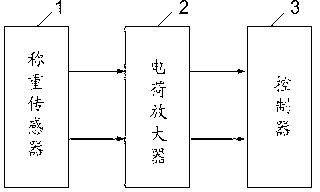
[0020] see figure 1 , is a schematic structural diagram of the vehicle dynamic weighing system in the embodiment of the present invention. The vehicle dynamic weighing system of the present invention includes a load cell 1, a charge amplifier 2 and a controller 3, and the waveform signal generated by the load cell 1 when the wheels are rolling , is amplified by the charge amplifier 2 and transmitted to the controller 3, and the controller 3 calculates the vehicle w...


PUM


Abstract

The invention discloses a vehicle dynamic weighing system which comprises a weighing sensor, a charge amplifier and a controller. The weighing sensor comprises two quartz senor groups which are laid along the road direction in a stagger way; each quartz sensor group comprises two quartz piezoelectric sensors which are laid along the road direction; the two quartz piezoelectric sensors of the first quartz sensor group are arranged crosswise in tandem on the left side of a driveway; and the two quartz piezoelectric sensors of the second quartz sensor group are arranged crosswise in tandem on the right side of the driveway. When a vehicle passes through the weighing sensor, the controller calculates the vehicle weight values according to the waveform signals generated by the quartz sensors and averages the vehicle weight values to obtain the final vehicle weight value. Since the two groups of quartz sensors are arranged in parallel in the stagger way, the vehicle dynamic weighing system can conduct effective processing on abnormal occasions, that is, when the vehicle passes through the road section in which the sensors are laid in uneven speed or in a zigzag manner, the vehicle dynamic weighing system can average the calculation results of the two groups of quartz sensors to revise the deviation so as to enable the weighing result to be more accurate.

Description

technical field [0001] The invention relates to the weighing field, in particular to a vehicle dynamic weighing system. Background technique [0002] The dynamic weighing of existing vehicles generally uses a single row of quartz sensors to cover the lane. The quartz sensors detect the pressure and speed of each axle of the vehicle passing on the road surface, and then use an embedded computer to calculate the weight of each axle and the overall weight of the vehicle. gross vehicle weight. Its calculation formula is: [0003] Axle weight = axle speed / sensor width * piezoelectric waveform integral area * correction factor [0004] The total weight of the vehicle = the sum of the axle loads [0005] It can be seen from the above formula that when the vehicle passes at a non-uniform speed or takes the "S" route, this will lead to deviations in the weighing results. Therefore, the single row of quartz sensors cannot solve the weighing deviation caused by abnormal passing o...

Claims


Application Information

Patent Timeline
Patent Type & Authority Patents(China)
IPC IPC(8): G01G19/03
Inventor 胡平黄晓吕奎
Owner SICHUAN XINGDA MINKO ELECTR MECHANICAL ENG
Learn More