
Liquid crystal lens

A technology of liquid crystal lens and liquid crystal layer, applied in optics, instruments, nonlinear optics, etc., can solve the problems of poor display effect and graininess of the picture, and achieve the effect of improving display effect, fine picture and reducing moiré.

Inactive Publication Date: 2012-12-05
SHENZHEN SUPER PERFECT OPTICS LTD
View PDF9 Cites 31 Cited by
  • Summary
  • Abstract
  • Description
  • Claims
  • Application Information

AI Technical Summary

Problems solved by technology

[0004] In the existing naked-eye stereoscopic display, a large number of moiré patterns will be generated between the light of the display and the liquid crystal lens, making the picture grainy and the display effect is not good

Method used


Image

  • Liquid crystal lens
  • Liquid crystal lens
  • Liquid crystal lens

Examples


Embodiment Construction

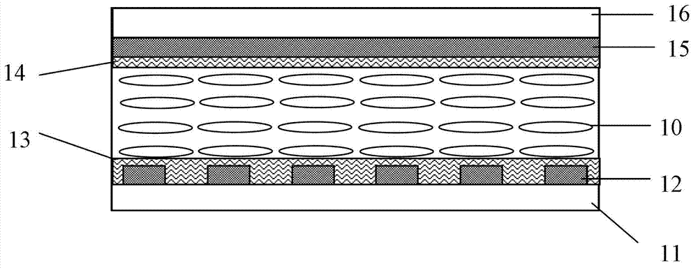
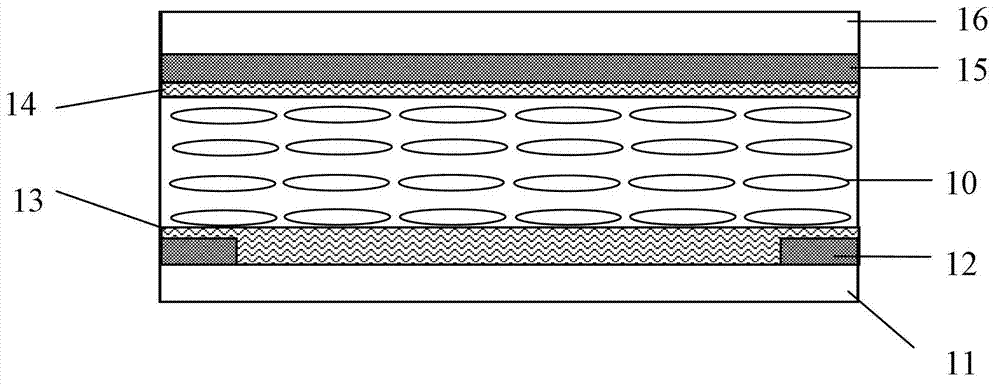
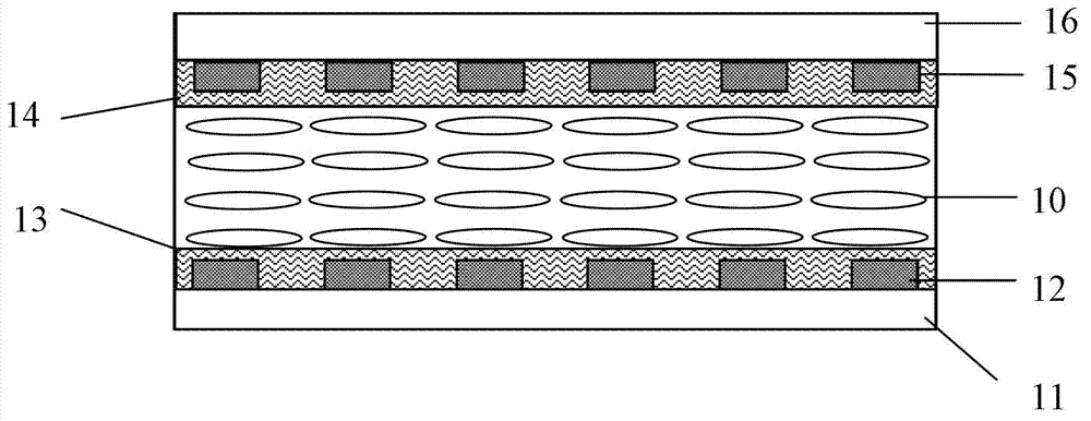
[0029] figure 1 It is a cross-sectional view of the liquid crystal lens of this embodiment, the first substrate 11 and the second substrate 16 are arranged in parallel at a predetermined distance, the first electrode 12 is arranged on the inner surface of the first substrate 11, and the inner surface of the second substrate 16 The second electrode 15 is arranged on the inner surface of the first electrode 12, the first alignment layer 13 is arranged on the inner surface of the second electrode 15, the second alignment layer 14 is arranged on the inner surface of the second electrode 15, and the first alignment layer 13 and the second alignment layer The rubbing directions of the layers 14 are perpendicular to each other; the parallel nematic liquid crystal 10 (liquid crystal layer 10) is filled between the first alignment layer 13 and the second alignment layer 14.

[0030] Such as Figure 18 As shown, when different voltages are applied to each electrode of the first electr...


PUM


Abstract

The invention discloses a liquid crystal lens comprising a first basal plate, a second basal plate, a first electrode, a second electrode, a first alignment layer, a second alignment layer and a liquid crystal layer, wherein the first basal plate and the second basal plate are arranged in parallel at a preset distance, the first electrode is arranged on the first basal plate, the second electrode is arranged on the second basal plate, the first alignment layer is covered on the first electrode, the second alignment layer is covered on the second electrode, and the liquid crystal layer is arranged between the first alignment layer and the second alignment layer. According to the liquid crystal lens disclosed by the invention, the aim of reducing Moires generated between the light rays of a display and the liquid crystal lens is realized by adopting various electrodes with different forms, so that the picture is more exquisite. Therefore, the display effect of stereo display is enhanced.

Description

technical field [0001] The invention relates to the technical field of naked-eye stereoscopic display, in particular to a liquid crystal lens. Background technique [0002] In recent years, 3D technology has developed rapidly. 3D movies and 3D games have been launched one after another. The three-dimensional display technology with volume characteristics has gained room for rapid development. [0003] Among the many technologies for realizing 3D stereoscopic display, the naked-eye stereoscopic display is favored in the field of 3D stereoscopic display due to the advantage that the viewer does not need to wear special special glasses. [0004] In the existing naked-eye stereoscopic display, a large number of moiré patterns will be generated between the light of the display and the liquid crystal lens, which will make the picture grainy and the display effect is not good. Contents of the invention [0005] The technical problem to be solved by the present invention is to p...

Claims


Application Information

Patent Timeline
Patent Type & Authority Applications(China)
IPC IPC(8): G02F1/29G02F1/1343G02B27/22
Inventor 陈寅伟宋磊刘宁戈张
Owner SHENZHEN SUPER PERFECT OPTICS LTD
Learn More