Electronic sphygmomanometer

An electronic sphygmomanometer and touch pressure technology, which is applied in the direction of cardiac catheterization, etc., can solve the problems of small locking parts, damage to the overall appearance, and easy loss during loading and unloading, and achieve the effects of simple structure, avoiding misoperation, and reliable connection

Active Publication Date: 2012-12-12
ANDON HEALTH +1
View PDF7 Cites 12 Cited by
  • Summary
  • Abstract
  • Description
  • Claims
  • Application Information

AI Technical Summary

Problems solved by technology

Although adopting the above-mentioned structure can bring certain convenience, the above-mentioned locking part is small in size and easy to be lost during loading and unloading, thereby losing its function; a part of the locking part is exposed outside the casing, which damages the overall appearance and also brings a detachable reminder to the user , easy to cause user misoperation, and easy to lose due to inadvertent touch or collision

Method used


Image

  • Electronic sphygmomanometer
  • Electronic sphygmomanometer
  • Electronic sphygmomanometer

Examples


Embodiment Construction

[0036] Below in conjunction with accompanying drawing and preferred embodiment, structure, feature and effect thereof of the present invention are described in detail as follows:

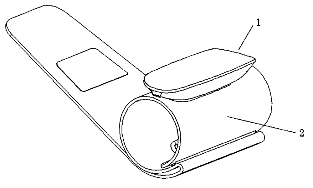
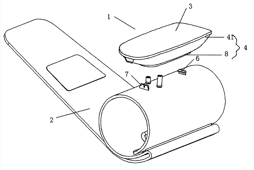
[0037] Such as Figure 1 to Figure 7 As shown, the electronic sphygmomanometer of this embodiment includes: a main body 1 and a cuff 2, and the main body includes an upper casing 3 and a lower casing 4. Although the inside thereof is not shown, a known blood pressure measurement unit is arranged inside it, The main components such as the control unit and the air pump are provided with a display unit and an operation unit composed of liquid crystals on the surface.

[0038] The cuff of this embodiment mainly includes a sleeve body, which can be made of materials such as cloth; an airbag, which is arranged inside the sleeve body; and a liner 5, which is arranged inside the sleeve body and outside the airbag, which is a known technology I won't repeat them here.

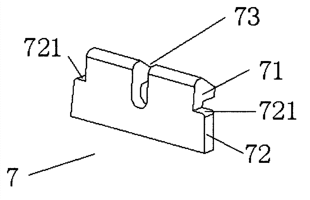
[0039] In this embodiment, in order ...


PUM


Abstract

The invention provides an electronic sphygmomanometer which comprises a body and a cuff, wherein the cuff comprises a lining plate; at least one fixed clamping hook is arranged at one end of the lining plate, and a releasable clamping hook is arranged at the other end of the lining plate; each of the fixed clamping hook and the releasable clamping hook comprises a hooking part and a supporting arm; shoulder parts are extended from two ends of the supporting arm of the releasable clamping hook, and the releasable clamping hook is provided with a gap; the bottom of a lower shell is provided with a fixed end clamping groove and a releasable end clamping groove corresponding to the fixed clamping hook and the releasable clamping hook, and a blocking part is arranged on one side of the releasable end clamping groove buckled with the hooking part; an elastic sheet is arranged close to the releasable end clamping groove on the inner surface of the bottom of the lower shell, the elastic sheet comprises a touch part and an elastic part, and the touch part covers a part of the releasable end clamping groove; and the side wall of the lower shell is provided with a through hole, and the through hole is opposite to the touch end face of the touch part of the elastic sheet through the gap in the releasable clamping hook. The electronic sphygmomanometer ensures reliable connection between the cuff and the body in use, is convenient to detach and simple in structure, and is integrally miniaturized.

Description

technical field [0001] The invention relates to an electronic sphygmomanometer, in particular to a connection method between a main body of the electronic sphygmomanometer and a cuff. Background technique [0002] Currently commercially available electronic sphygmomanometers generally adopt the structure of a body and a cuff, especially in wrist sphygmomanometers. A hook protrudes from the sleeve, and the body is equipped with pumps and valves for inflating and contracting the above-mentioned airbag. There is a slot corresponding to the hook on the bottom of the lower shell of the body, and the hook extends into the slot and the lower shell of the body. Snapping, using the above structure requires a lot of force to disassemble. In the worst case, the hook or slot will be damaged, and it is not reliable enough to fix the body and cuff only by the hook. When the tester adjusts the position of the body during use, the Force may cause the main body and the cuff to separate, the...

Claims


Application Information

Patent Timeline
Patent Type & Authority Applications(China)
IPC IPC(8): A61B5/0225
Inventor 亢海生段冰郭颖
Owner ANDON HEALTH
Why Eureka
Try Eureka