
Method and system for generating rail transit emergency evacuation routes

An emergency evacuation and rail transit technology, applied in railway traffic management, transportation center control systems, railway car body components, etc., can solve the problems of reduced emergency evacuation efficiency, congestion of evacuation routes, low emergency evacuation efficiency, etc. The effect of evacuation efficiency

Active Publication Date: 2015-10-28
QINGDAO HISENSE TRANS TECH
View PDF5 Cites 0 Cited by
  • Summary
  • Abstract
  • Description
  • Claims
  • Application Information

AI Technical Summary

Problems solved by technology

[0004] It can be seen from the above that the rail transit emergency evacuation route pre-installed in the evacuation guidance system can only provide the pre-set rail transit emergency evacuation route, and cannot be based on the spatial location of the disaster scene, the affected area of ​​the disaster scene, and the boundary of the disaster scene such as the passage. In the actual situation, the dynamic generation of emergency evacuation routes for rail transit cannot be adjusted dynamically in real time with the occurrence of disaster scenarios, making emergency evacuation inefficient; The evacuation board cannot guide the evacuation passengers with an intuitive and overall emergency evacuation route, which will easily cause panic and disorder in the emergency evacuation passengers, thereby affecting the evacuation efficiency; furthermore, there is only one pre-designed emergency evacuation route for rail transit. , emergency evacuation passengers can only evacuate along a pre-designed rail transit emergency evacuation route, which is more likely to lead to congestion of the evacuation route, further reducing the efficiency of emergency evacuation

Method used


Image

  • Method and system for generating rail transit emergency evacuation routes
  • Method and system for generating rail transit emergency evacuation routes
  • Method and system for generating rail transit emergency evacuation routes

Examples


Embodiment Construction

[0065] The technical solutions of the various embodiments of the present invention will be clearly and completely described below in conjunction with the accompanying drawings. Apparently, the described embodiments are only some of the embodiments of the present invention, not all of them. Based on the embodiments of the present invention, all other embodiments obtained by persons of ordinary skill in the art without making creative efforts belong to the protection scope of the present invention.

[0066] The existing rail transit emergency evacuation routes are all pre-designed, and by installing emergency lights and guide boards on the platform and intervals, or installing an independent evacuation guidance system, the rail transit emergency evacuation routes are instructed, and the rail transit emergency The evacuation route generation mode is relatively fixed, and the instruction method is relatively simple. It cannot form a dynamic rail transit emergency evacuation route a...


PUM


Abstract

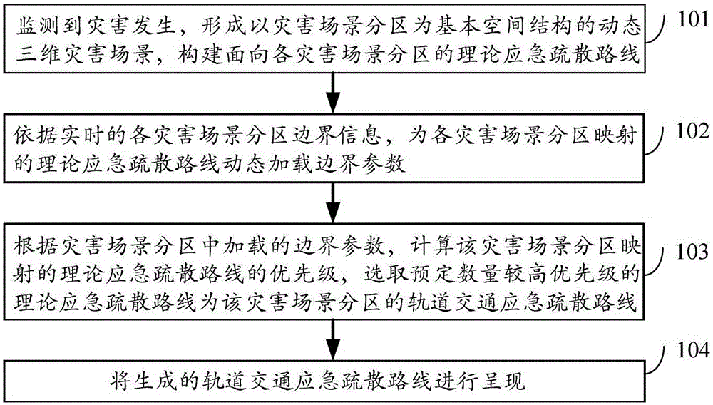
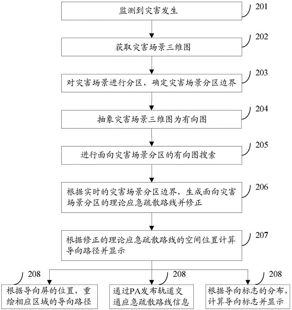
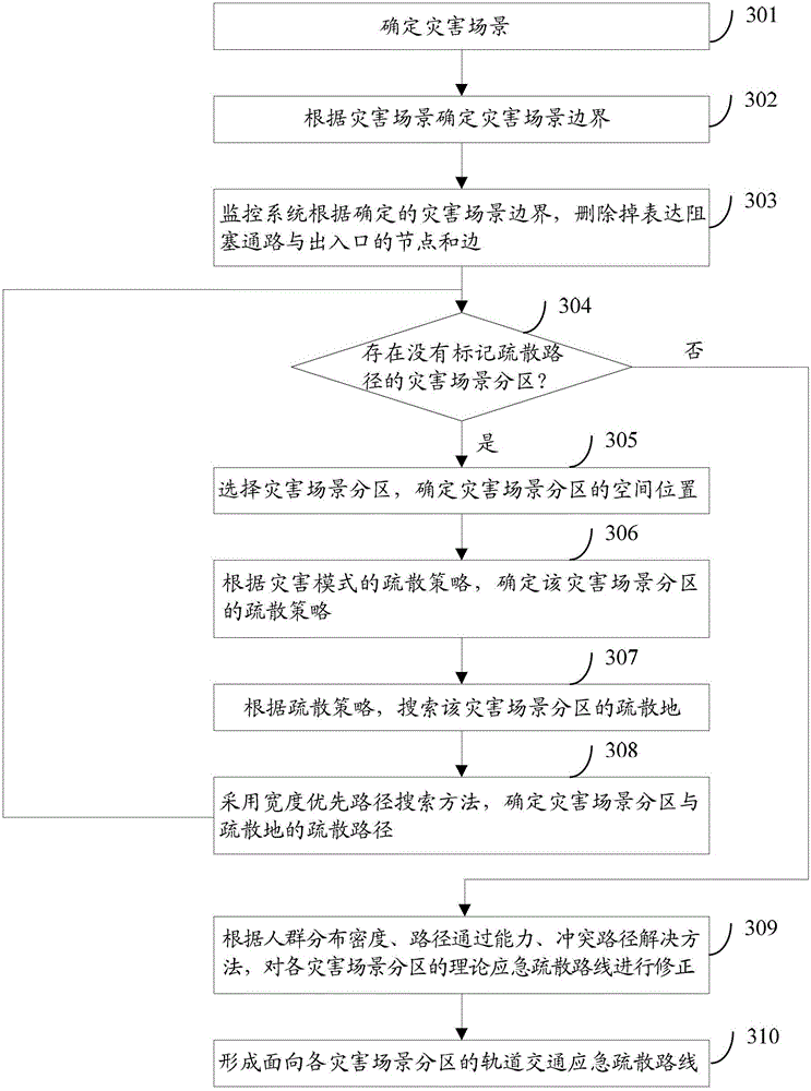
The invention discloses a method and a system for generating rail transit emergency evacuation routes. The method comprises the following steps of: when occurrence of a disaster is monitored, forming a dynamic three-dimensional disaster scene which uses disaster scene sub-zones as basic spatial structures, and constructing theoretical emergency evacuation routes from each disaster scene sub-zone to an evacuation site; according to real-time boundary information of each disaster scene sub-zone, dynamically loading boundary parameters to the theoretical emergency evacuation routes which are mapped to each disaster scene sub-zone; and according to the boundary parameters loaded in the disaster scene sub-zones, computing the priorities of the theoretical emergency evacuation routes which are mapped to the disaster scene sub-zones, and selecting a preset quantity of higher-priority theoretical emergency evacuation routes as the rail transit emergency evacuation routes for the disaster scene sub-zones. By using the method and the system for generating rail transit emergency evacuation routes, the emergency evacuation efficiency can be improved.

Description

technical field [0001] The invention relates to rail transit safety technology, in particular to a method and system for generating rail transit emergency evacuation routes. Background technique [0002] With the rapid development of urban rail transit, the increasingly perfect functions of subway platforms and the one-way operation of subways, rail transit has become the preferred means of transportation for people in modern cities. A large number of passengers commute between subway platforms and subway sections every day. Since rail transit has the characteristics of complex underground structure, closed space, huge flow of people and difficult evacuation, once natural disasters, man-made sabotage, equipment failure and other sudden disasters occur, how to quickly and safely evacuate passengers has become an important issue in modern rail transit. Important functions for operating the service. [0003] The existing rail transit emergency evacuation route is pre-generated...

Claims


Application Information

Patent Timeline
Patent Type & Authority Patents(China)
IPC IPC(8): B61L27/00
Inventor 杜军威万思军阎嵩廖常斌
Owner QINGDAO HISENSE TRANS TECH
Learn More