
Water injection and air inflation integrated water rocket launching device

A launcher and water rocket technology, which is applied in the direction of educational appliances, instruments, teaching models, etc., can solve the problems of large errors, inconsistent flight attitudes, unstable center of gravity of water rockets, etc., and achieve the effect of small errors

Inactive Publication Date: 2012-12-12
施胜南
View PDF5 Cites 8 Cited by
  • Summary
  • Abstract
  • Description
  • Claims
  • Application Information

AI Technical Summary

Problems solved by technology

[0003] The purpose of the present invention is to provide a water injection and air-filled integrated water rocket launching device to solve the problem that the center of gravity of the existing water rocket is unstable, the flight attitude during launch is inconsistent with the pre-designed flight attitude, and the error is large, thereby affecting the experimental effect. question

Method used


Image

  • Water injection and air inflation integrated water rocket launching device

Examples


specific Embodiment approach 1

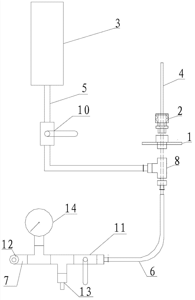
[0007] Specific implementation mode one: combine figure 1 Describe this embodiment, the device of this embodiment includes launch pad 1 and water sleeve 2, is characterized in that described device also includes funnel 3, first pipeline 4, second pipeline 5, third pipeline 6, The fourth pipeline 7, the three-way 8, the first valve 10, the second valve 11 and the air needle 13, the upper end of the first pipeline 4 passes through the launch pad 1 and the water sleeve 2 successively and is arranged in the water rocket body and is located in the water rocket body. In the upper part of the rocket body, the lower end of the first pipeline 4 communicates with the lower end of the second pipeline 5 and one end of the third pipeline 6 through a tee 8, and the upper end of the second pipeline 5 communicates with the lower end of the funnel 3. The second pipeline 5 is provided with a first valve 10, the other end of the third pipeline 6 communicates with one end of the fourth pipeline 7...

specific Embodiment approach 2

[0009] Specific implementation mode two: combination figure 1 Describe this embodiment, the device of this embodiment also includes a barometer 14, the fourth pipeline 7 is provided with a barometer 14, when this structure is inflated, grasp the value of the air pressure inside the water rocket, and avoid the risk of bursting when the pressure is too high The problem. Other implementation manners are the same as the specific implementation manner 1.

specific Embodiment approach 3

[0010] Specific implementation mode three: combination figure 1 Describe this embodiment, the device of this embodiment also includes regulating valve 12, and the other end of the fourth pipeline 7 communicates with regulating valve 12, and the effect of this regulating valve 12 is to adjust the air pressure in the water rocket body to the specified air pressure, and can also unload Drop the pressure inside the arrow. Other implementation manners are the same as the specific implementation manner 1.

[0011] Working principle: 1. Connect the connecting parts of the present invention;

[0012] 2. Insert the nozzle of the water rocket body into the water sleeve 2 and lock it;

[0013] 3. Open the second valve 11 and the regulating valve 12;

[0014] 4. After the launch pad 1 is adjusted to the horizontal position, the water rocket is set vertically with the launch pad 1. After opening the first valve 10, pour water into the funnel 3, and the water will flow into the body of ...


PUM


Abstract

The invention relates to a physics teaching tool, in particular to a water injection and air inflation integrated water rocket launching device. The device solves the problems that the center-of-gravity position of the existing water rocket is unstable, the flying attitude in launching is inconsistent with the pre-designed flying attitude and has relatively great error and consequently the experimental effect is influenced. The upper end of a first pipeline sequentially penetrates through a launching pad and a water sleeve and is arranged in the water rocket body and located at the upper part of the water rocket body; the lower end of the first pipeline is communicated with the lower end of a second pipeline and one end of a third pipeline through a tee joint respectively; the upper end of the second pipeline is communicated with the lower end of a funnel; the second pipeline is provided with a first valve; the other end of the third pipeline is communicated with one end of a fourth pipeline; and the fourth pipeline is provided with a second valve and an air needle respectively. The device disclosed by the invention is applied to physics teaching.

Description

technical field [0001] The invention relates to a physics teaching tool, in particular to a water-injecting and air-filling integrated water rocket launching device. Background technique [0002] Most of the current water rocket launching devices are made by installing an air needle on the base of the water-through sleeve, and directly inflate the air needle with an air pump. There are three problems in the use of this launching device: 1. When launching, the water rocket must be Put it upside down, inject the specified amount of water into the bottle, and then insert the water rocket nozzle into the water sleeve to lock it. This process will cause water to flow out of the rocket body. If it is a multi-stage water rocket, it will cause water to flow into the bottom. In the above rocket body; 2. For multi-stage water rockets, when the rocket body is pressurized, the water in the bottom bottle will be brought to the upper bottle by the air filled in and cannot be left behind, ...

Claims


Application Information

Patent Timeline
IPC IPC(8): G09B23/08
Inventor 施胜南刘通学金铁钢杨昭王洪秀侯少杰朱砂李萌
Owner 施胜南
Learn More