Area light source device and display device

a technology of display device and light source, which is applied in the direction of illuminated signs, display means, instruments, etc., can solve the problems of difficult to vary the amount of light emitted, and difficulty in uniform light emitted

Inactive Publication Date: 2013-01-08
SONY CORP
View PDF24 Cites 28 Cited by
  • Summary
  • Abstract
  • Description
  • Claims
  • Application Information

AI Technical Summary

Benefits of technology

[0010]In this configuration, the light guide plate has one surface that serves as the transmissive surface and another surface that is on the opposite side from the transmissive surface and in which the plurality of the recessed portions are provided. The at least two light-emitting elements that are accommodated in each of the recessed portions emit light in the direction in which the light guide plate extends, and are disposed such that they emit light in different directions. Therefore, directing a light-emitting face of any one of the light-emitting elements such that it faces a given light-emitting area makes it possible to cause light to be emitted uniformly within the light-emitting area and also makes it possible to cause light to be emitted only within the specific light-emitting area.
[0025]In this configuration, in the display device that includes the display panel and the area light source, an image is displayed on the display panel. The light guide plate has one surface that serves as the transmissive surface and another surface that is on the opposite side from the transmissive surface and in which the plurality of the recessed portions are provided. The at least two light-emitting elements that are accommodated in each of the recessed portions emit light in the direction in which the light guide plate extends, and are disposed such that they emit light in different directions. Therefore, directing a light-emitting face of any one of the light-emitting elements such that it faces a given light-emitting area makes it possible to cause light to be emitted uniformly within the light-emitting area and also makes it possible to cause light to be emitted only within the specific light-emitting area.
[0031]According to the present invention, an area light source device and a display device can be provided that are capable of performing uniform light emission in each of the light-emitting areas in the light guide plate.

Problems solved by technology

This gives rise to irregularities in the contrast of the light guide plate per unit area and makes it difficult to emit light uniformly.
This makes it difficult to vary the amount of light that is emitted such that the brightnesses of the light-emitting areas and the non-light-emitting areas will be clearly differentiated in each block within the plane of the light guide plate.

Method used


Image

  • Area light source device and display device
  • Area light source device and display device
  • Area light source device and display device

Examples


Embodiment Construction

[0044]Hereinafter, preferred embodiments of the present invention will be described in detail with reference to the appended drawings. Note that, in this specification and the appended drawings, structural elements that have substantially the same function and structure are denoted with the same reference numerals, and repeated explanation of these structural elements is omitted. Note that the explanation will cover the points below in order.

[0045]1. Configuration of a Display Device According to an Embodiment of the Present Invention

[0046]2. Configuration of a Light Guide Plate

[0047]3. Positional Relationships Between a Hexagonal Light-emitting Area and Light-emitting Diodes in Recessed Portions

[0048]4. Other Examples of Arrangements of Light-emitting Areas and Light-emitting Diodes

[0049]1. Configuration of a display device according to an embodiment of the Present Invention

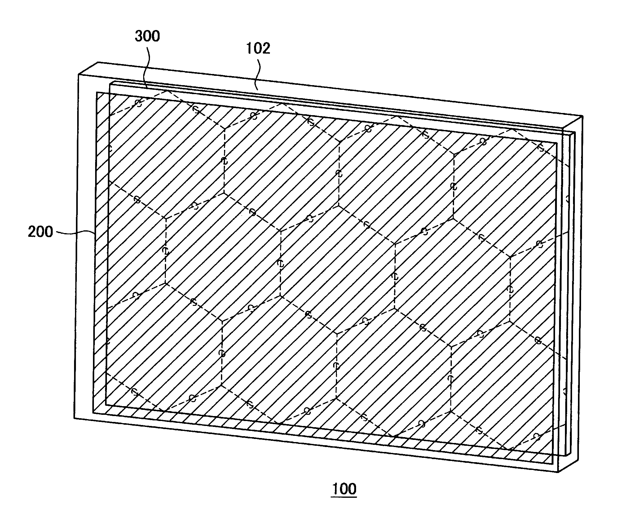
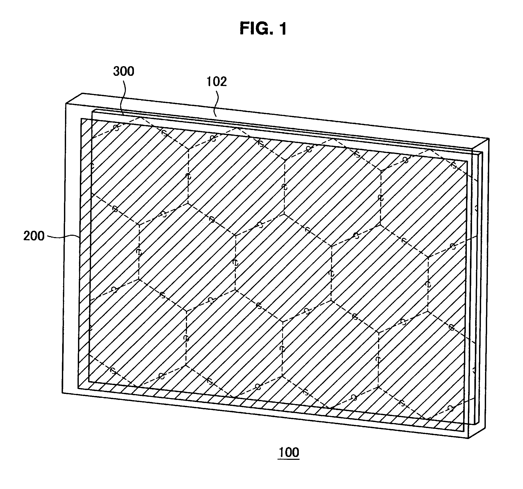
[0050]FIG. 1 is an oblique view that shows a configuration of an image display device 100 according to an emb...


PUM


Abstract

An area light source device according to the present invention includes a plate-shaped light guide plate that has one surface that serves as a transmissive surface and another surface that is on the opposite side from the transmissive surface and in which a plurality of recessed portions are provided. The area light source device also includes at least two light-emitting diodes that are accommodated in each of the recessed portions, that emit light in a direction in which the light guide plate extends, and that are disposed such that they emit light in different directions. In this configuration, directing a light-emitting face of any one of the light-emitting diodes such that it faces a given light-emitting area makes it possible to cause light to be emitted uniformly within the light-emitting area and also makes it possible to cause light to be emitted only within the specific light-emitting area.

Description

BACKGROUND OF THE INVENTION[0001]1. Field of the Invention[0002]The present invention relates to an area light source and a display device.[0003]2. Description of the Related Art[0004]Technologies are known by which light-emitting diodes are provided in recessed portions that are provided in a light guide plate in a backlight device of a liquid crystal display device, such that light is emitted from the light guide plate, as described in Japanese Patent Application Publication No. JP-A-8-136917 and Japanese Patent Application Publication No. JP-A-2006-227423, for example.[0005]Technologies are also known by which a display screen is divided into a plurality of blocks and the backlight brightness of each of the blocks is varied according to an input image signal, as described in Japanese Patent Application Publication No. JP-A-2005-17324 and Japanese Patent Application Publication No. JP-A-11-109317, for example.SUMMARY OF THE INVENTION[0006]However, with the technologies that are de...

Claims


Application Information

Patent Timeline
Patent Type & Authority Patents(United States)
IPC IPC(8): G09F13/08
CPCG02B6/0021G02B6/0031G02B6/0068G02B6/0036
Inventor NAKAMURA, TOMOHARU
Owner SONY CORP
Why Eureka
Try Eureka