Refraction-type led ceiling lamp

a technology of led ceiling lamps and diodes, which is applied in the direction of fixed installation, lighting and heating equipment, instruments, etc., can solve the problems of waste heat generated correspondingly, difficult to define the illumination angle of an ordinary lamp-set, and inferior color rendering index of led lamps, so as to achieve the effect of utilizing light flux

Inactive Publication Date: 2011-06-07
广东佳兆业佳云科技股份有限公司
View PDF6 Cites 25 Cited by
  • Summary
  • Abstract
  • Description
  • Claims
  • Application Information

AI Technical Summary

Benefits of technology

[0010]With the principles of light reflection and refraction, the present invention utilizes angle guidance and a reflection design which corresponds with an unequal optical path to allow a ceiling lamp to have an effect of uniform intensity of illumination and lumen, to define a projection area and to effectively utilize a light flux.
[0011]The present invention utilizes a slab-shape light guide plate, with at least two parallel and opposite entrance surfaces to allow light beams generated from a series of excitation units to enter into the light guide plate oppositely. The light guide plate is formed with a refraction surface to emit the light beam and with another surface which is a reflection surface. The reflection surface is provided with plural reflection elements which are arranged in a matrix. A chip size of the reflection element decreases gradually by a geometric series toward the entrance surface, from a breadth center; whereas a gap between the reflection elements increases gradually by a geometric series. In principle, the chip size of the reflection elements at the breadth center is 2, gradually decreasing to 1 for the chip size of the reflection elements at a periphery of the breadth. On the other hand, the gap between the reflection elements at the center of the reflection breadth is 1, gradually increasing to 2 for the gap between the reflection elements at the periphery of the breadth. To allow the light beams that are emitted from the excitation units to be depleted gradually when the beams reach to the center in progression of the optical path, a density of the reflection elements can be increased at the center to forcefully enhance the reflection operation, enabling the lumen of the light beams emitted from the entire refraction surface to be uniform. The reflection element is in a convex shape and is provided with an inward reflection curve. The reflection element can change a direction of and reflect the light beam emitted by the excitation unit at a fixed angle into a vertical line close to the refraction surface, such that the optical path of the excitation unit is bended by about 90°. Therefore, in terms of the illumination angle, the ceiling lamp can be effectively defined as projecting downward to guide the light flux to illuminate downward in full intensity approximately.
[0012]The present invention focuses on an effective utilization of directionality of the total light flux, allowing the light beams to be emitted uniformly for the entire refraction surface and effectively dissipating the waste heat of the excitation units. Accordingly, a fiber light guide plate is designed, wherein at least two parallel entrance surfaces provide a corresponding design of the excitation units arranged in a series, with light energy generated by the excitation units entering from the entrance surfaces at two parallel sides, being reflected and traveling forward in the light guide plate. The light beams that enter into the entrance surfaces are divided into multiple orientations and basically, a size of the light guide plate can be chosen according to the emission angle of the excitation unit. For an ordinary LED excitation unit, the emission angle is between 20° and 60°. After the emitted light beam has entered from the entrance surfaces of the light guide plate, a part will operate on the refraction surface, whereas other part will operate on the reflection surface. After reaching the reflection surface, the light beam is reflected according to a normal of the reflection surface to travel toward the refraction surface. On the other hand, the reflection surface is provided with the reflection elements which are provided with the reflection curves. The reflection curve corresponds to the light beam that enters from the entrance surface and is bended effectively, allowing an emission route refracted from the reflection beam to approach to a vertical line of the refraction surface, thereby transforming the light beam generated by the excitation unit by about 90°. Therefore, the illumination angle of the ceiling lamp can be oriented effectively to define a limited angle, the light flux will not be loaded unnecessarily, and a frame of the excitation unit can be utilized directly as a heat conduction mechanism to effectively dissipate the waste heat generated, with an assembly part being formed by utilizing the frame to facilitate installing on the ceiling to illuminate on a ground. In addition, the uniform brightness can be achieved and the illumination angle can be defined, which are the primary object of the present invention, by arranging the reflection elements on the reflection surface in a matrix, with the gap increasing gradually by a geometric series from the center and the chip size of the reflection elements decreasing gradually from the center.

Problems solved by technology

In addition, due to an error in a manufacturing process or of a material, each LED lamp will have a different illumination efficiency and wavelength, and a color render index of the LED lamp will be inferior.
Although utilization of light energy can be satisfied through defining the illumination angle to prevent from unnecessary loading to the light energy, it is difficult to define the illumination angle for an ordinary lamp-set.
However, the LED that is applied in the household illumination should operate at a high power; hence, waste heat will be generated correspondingly.
In addition, a working temperature of an LED lamp-set system cannot be too high and a total temperature difference should not be higher than 15° to prevent from thermal strain degradation of material by heat or prevent the material from undergoing a vicious cycle by a resistance factor that the efficiency is lost.
However, as the excitation unit is a point source of light, appearance will offend eyes and lumen or a color temperature will be non-uniform due to the manufacturing error.
Nevertheless, for the indoor illumination that focuses on the energy saving, the loss from the light beam pre-transformation operation does not facilitate a general implementation.

Method used


Image

  • Refraction-type led ceiling lamp
  • Refraction-type led ceiling lamp
  • Refraction-type led ceiling lamp

Examples


Embodiment Construction

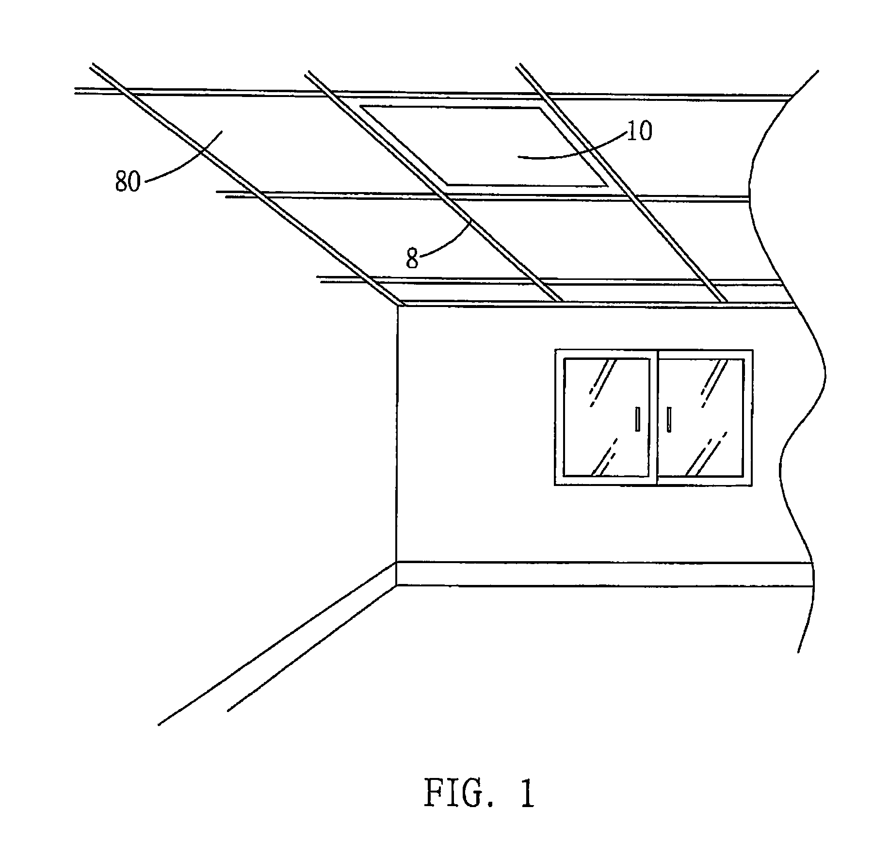
[0031]Referring to FIG. 1, a ceiling lamp 10 of the present invention is applied to an indoor ceiling, e.g. of a configuration with light-weight steel frames 8. The ceiling lamp 10 has a same area as a partition panel 80 and therefore can be easily assembled at the light-weight steel frame 8 to form illumination on a ground.

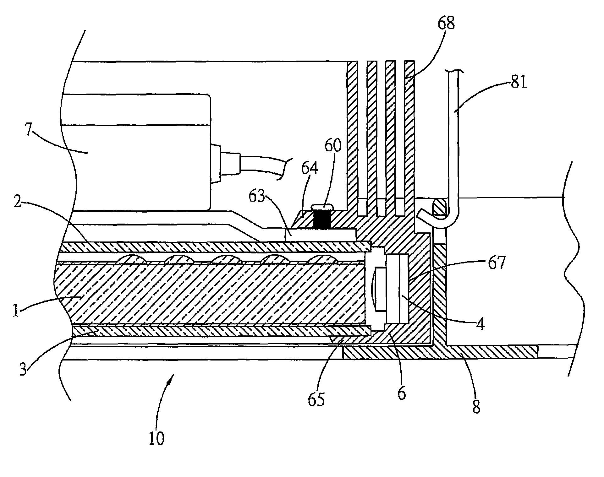
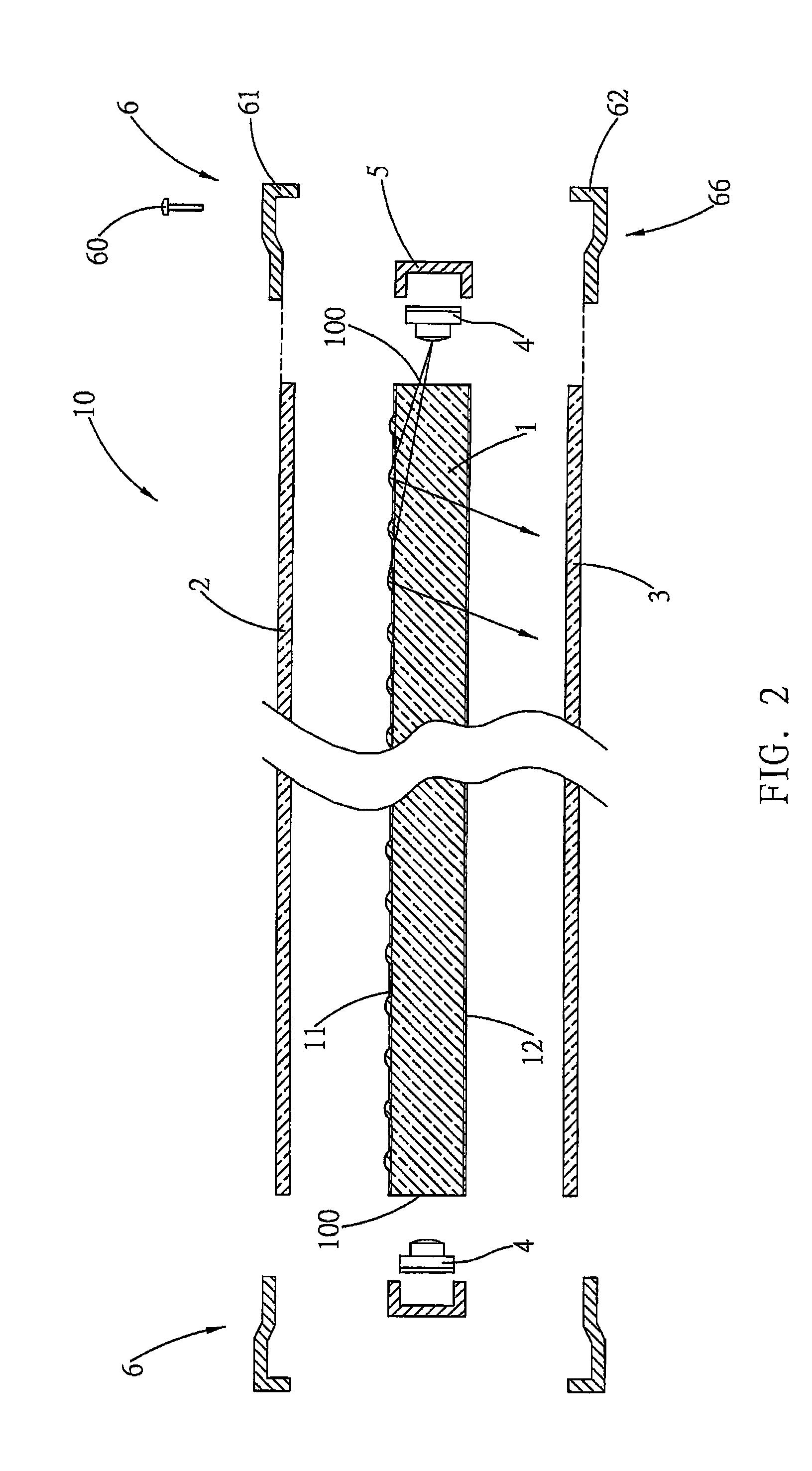
[0032]Referring to FIG. 2, the ceiling lamp 10 of the present invention comprises primarily a light guide plate 1, wherein two opposite sides are parallel to each other and are formed respectively with an entrance surface 100, an exterior part of the entrance surface 100 is provided correspondingly with an LED excitation unit 4 which forms a series, and an exterior part of which is a heat conduction unit 5 to expel waste heat, forming a waste heat dissipating path. Lower and upper sides of the light guide plate 1 are formed respectively with a refraction surface 12 and a reflection surface 11. A light beam generated by the excitation unit 4 enters from the entran...


PUM


Abstract

A refraction-type LED ceiling lamp, especially a plate-type ceiling lamp which is used on an indoor ceiling, includes primarily a fiber light guide plate, a reflection surface of which is provided with multiple chip-shape reflection elements, distributed in arrays. A chip size of the reflection elements decreases gradually toward an entrance surface by a geometric series; whereas, a gap between the reflection elements increases gradually. A reflection curve of the reflection element allows light to be projected out uniformly and a required illumination angle to be achieved.

Description

BACKGROUND OF THE INVENTION[0001]a) Field of the Invention[0002]The present invention relates to a refraction-type LED (Light Emitting Diode) ceiling lamp, and more particularly to a plate-type ceiling lamp which is used on an indoor ceiling with a limited projection angle to project brilliance on a limited area on a ground, forming uniform light beams of emission and effectively defining a projection area. In addition, the ceiling lamp can be assembled on the ceiling successfully and can be cooled spontaneously.[0003]b) Description of the Prior Art[0004]In a wave of saving energy and reducing carbon dioxide emission, energy-saving illumination equipment has become a mainstream in household or office illumination. A fluorescent light and an LED lamp can save energy, yet as an existing LED lamp is deployed as a dot-matrix distribution, the LED lamp is a point source of light in the dot-shape distribution if viewing from outside. In addition, due to an error in a manufacturing process...

Claims


Application Information

Patent Timeline
Patent Type & Authority Patents(United States)
IPC IPC(8): F21S8/00
CPCG02B6/0043G02B6/0055G02B6/0061F21S8/026F21Y2101/02F21V2200/20G02B6/0073F21Y2105/00G02B6/0068F21Y2115/10
Inventor ZHOU, JIAN-LIN
Owner 广东佳兆业佳云科技股份有限公司
Why Eureka
Try Eureka