An adaptive synchronous flashing beacon light and its implementation method

An implementation method and technology for beacon lights, applied in the field of beacon lights, can solve the problems of unsuitable general use, high cost, inability to realize synchronous flashing, etc., and achieve the effect of being suitable for popular use and low cost

Inactive Publication Date: 2015-12-16
罗柏令
View PDF4 Cites 0 Cited by
  • Summary
  • Abstract
  • Description
  • Claims
  • Application Information

AI Technical Summary

Problems solved by technology

At present, the synchronous flashing control methods of aviation obstruction lights and navigation lights mainly include the following: one is the main and auxiliary light control method, such as figure 1 As shown, one main light controls N sub-lights, and flashes synchronously under the control of the main light, but if the main light is broken, the whole system cannot work normally.
The other is the synchronous line connection control method, such as figure 2 As shown, connect the navigation lights together with wires, that is, connect the read / write ports of the lighting control unit, and communicate with each other to realize the synchronous flashing of the lights. However, if one of the navigation lights fails, a "broken link" will occur. " phenomenon appears, unable to achieve synchronous flash
There is also a GPS control method, such as image 3 As shown, each beacon light is equipped with GPS and GPS receiving antenna, and uses the pulse signal of GPS to flash synchronously. However, this control method is expensive and the control process is relatively complicated, so it is not suitable for general use.

Method used


Image

  • An adaptive synchronous flashing beacon light and its implementation method
  • An adaptive synchronous flashing beacon light and its implementation method
  • An adaptive synchronous flashing beacon light and its implementation method

Examples


Embodiment Construction

[0022] In order to make the purpose, technical solutions and advantages of the present invention clearer, the present invention is further described in detail below in conjunction with the embodiments and the accompanying drawings:

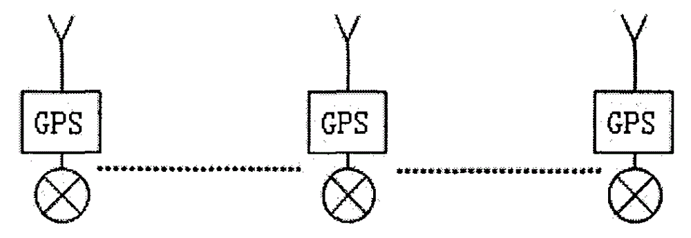
[0023] The adaptive synchronous flashing beacon light provided by the present invention, such as Figure 4 As shown in the figure, it includes a plurality of beacon light units L1 to LN. The plurality of beacon light units L1 to LN can be arranged in any shape according to the actual application, and each beacon light unit establishes a wireless transmission link through radio frequency circuits. To realize communication, it is not necessary to connect a signal line, the cost is low, and when one of the beacon light units is damaged, the signals of the remaining beacon light units still transmit to each other normally. like Figure 5 As shown, each beacon light unit includes a power source 5 and a controller 1, the power source 5 is connected to ...


PUM


Abstract

The invention provides an adaptive synchronous flashing beacon light and a realization method of the adaptive synchronous flashing beacon light. The adaptive synchronous flashing beacon light comprises a plurality of beacon light units, wherein beacon light units are all connected by wireless transmission links, each beacon light unit comprises a power supply and a controller, wherein the power supply is connected with a flashlight, and is used for electrifying the flashlight, an input of the controller is connected with a receiving module and an optical sensor, an output of the controller is connected with the receiving module and the power supply, and each beacon light unit is provided with an unique identification code. According to the adaptive synchronous flashing beacon light and the adaptive synchronous flashing beacon light realization method, the beacon light units receive signals sent by the other beacon light units by arranging the receiving modules adopting wireless transmission, and send signals to the other beacon light units through transmitting modules. The beacon light units select the beacon light units with the minimum identification codes to synchronously flash according to the identification code information and the unit identification code contained in the received signals, so that the synchronous flashing of the beacon light units can be realized.

Description

technical field [0001] The invention relates to a beacon light, in particular to an adaptive synchronous flashing beacon light and a method for realizing the same. Background technique [0002] According to national standards, high-rise buildings or other obstacles whose tops are 45 meters above the ground must be equipped with beacon lights to mark the highest point and edge contours of high-rise buildings or other obstacles or be used for navigation in sea and inland rivers. . In order to be different from the general purpose lighting, the beacon lights usually flash at a certain flash frequency. Therefore, the synchronous flash control of each beacon light is particularly important. At present, the synchronous flashing control methods of aviation obstruction lights and beacon lights mainly include the following: one is the control method of main and auxiliary lights, such as figure 1 As shown, one main light controls N sets of auxiliary lights, and flashes synchronously...

Claims


Application Information

Patent Timeline
Patent Type & Authority Patents(China)
IPC IPC(8): H05B37/02
Inventor 李峰
Owner 罗柏令
Why Eureka
Try Eureka