

Annular-space type centrifugal extractor, and application of same in oil phase-water phase separation technique of 4-amino diphenylamine reducing solution
A centrifugal extractor and annulus type technology, which is used in the purification/separation of amino compounds, solvent extraction of liquid solutions, organic chemistry, etc., can solve the problems of inconvenient disassembly and assembly, and achieve the effect of convenient operation and convenient adjustment
Active Publication Date: 2012-12-19
JIANGSU SINORGCHEM TECH CO LTD
View PDF4 Cites 6 Cited by
- Summary
- Abstract
- Description
- Claims
- Application Information
AI Technical Summary
Problems solved by technology
[0004] The present invention aims to provide a kind of annular gap type centrifugal extractor and its application in the oil phase and water phase separation process containing 4-aminodiphenylamine reducing
Method used
View moreImage
Smart ImageViewing Examples

Examples
 PUM
 Abstract
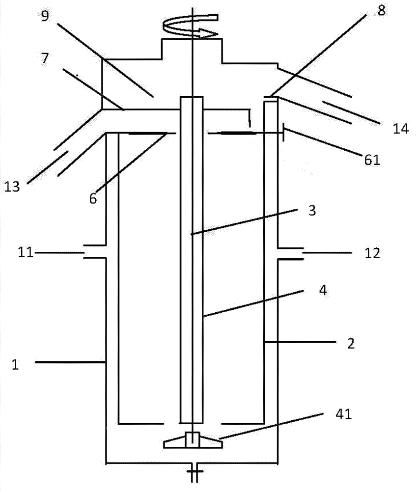
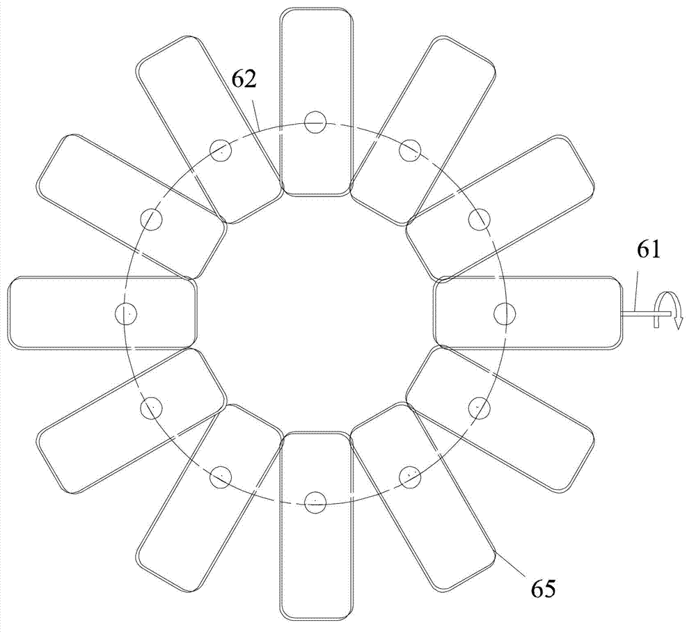
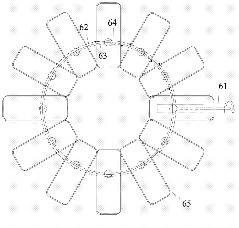
The invention provides an annular-space type centrifugal extractor and an application of the annular-space type centrifugal extractor in an oil phase-water phase separation technique of 4-amino diphenylamine reducing solution. The extractor comprises a shell, an inner cylinder, a collecting chamber, a rotating main shaft and a rotating drum; a light-phase inlet and a heavy-phase inlet are arranged on the outer wall of the shell at intervals, a light-phase outlet and a heavy-phase outlet are arranged on the outer wall of the shell at intervals, wherein the position of the light-phase outlet is higher than that of the light-phase inlet, and the position of the heavy-phase outlet is higher than that of the heavy-phase inlet; the inner cylinder is arranged in the shell, a channel is existent between the inner cylinder and the shell, a plurality of through holes are formed in the centre position of the lower bottom surface of the inner cylinder and are respectively communicated with the light-phase inlet and the heavy-phase inlet; the collecting chamber is arranged in the shell, arranged above the inner cylinder, and respectively communicated with the inner cylinder and the heavy-phase outlet; the rotating main shaft is arranged along the axial direction of the inner cylinder, and the upper end of the rotating main shaft runs through the collecting chamber and protrudes the shell; and the rotating drum is sleeved on the outer side of the rotating main shaft, the lower part of the collecting chamber is provided with a flow adjusting device which is used for adjusting the flow area of the liquid. With the adoption of the flow adjusting device, the flow of the light-phase liquid can be adjusted conveniently.
Description
technical field [0001] The invention relates to the field of extraction and separation, in particular to an annular gap centrifugal extractor and its application in the separation process of oil phase and water phase containing 4-aminodiphenylamine reducing liquid. Background technique [0002] An annular gap type centrifugal extractor commonly used at present has a shell, a light phase inlet, a heavy phase inlet, a light phase outlet and a heavy phase outlet located outside the shell. The shell has an inner cylinder, a collection chamber, a light-phase weir plate, a heavy-phase weir plate, a drum, a rotating main shaft and an overflow plate. The first overflow plate is a ring. When installed, it is fixed by the upper pressing plate and the lower pressing plate connected with the collection chamber, and at the same time, the drum passes through the middle hole of the overflowing plate. There is no contact between the overflow plate and the inner cylinder, and the separated ...
Claims
Login to View More Application Information
Patent Timeline
 IPC IPC(8): B01D11/04C07C211/55C07C209/86
Inventor陈新民武历保李春生林中影
OwnerJIANGSU SINORGCHEM TECH CO LTD