Pneumatic flaring machine

A flaring machine and pneumatic technology, applied in the field of flaring machines, can solve the problems of low work efficiency and high labor intensity, and achieve the effect of high work efficiency, low labor intensity and consistent clamping force

Inactive Publication Date: 2012-12-19
JIANGSU XINCHENG ELECTRICAL APPLIANCE GENERAL FACTORY
View PDF6 Cites 7 Cited by
  • Summary
  • Abstract
  • Description
  • Claims
  • Application Information

AI Technical Summary

Problems solved by technology

The clamping of the metal pipe to be flared and the pressing of the mold core and the expansion of the mold core in the prior art flaring machine are all done manually by workers, which has low work efficiency and high labor intensity.

Method used


Image

  • Pneumatic flaring machine
  • Pneumatic flaring machine
  • Pneumatic flaring machine

Examples


Embodiment Construction

[0014] The present invention will be further described below according to the accompanying drawings and in conjunction with the embodiments.

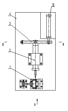
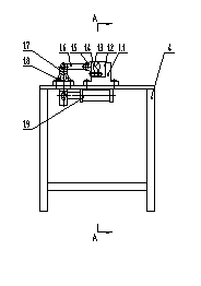
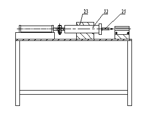
[0015] Pneumatic flaring machine shown in accompanying drawing, it comprises fixture 1, flaring frock 2, support 4, pneumatic drive mechanism 3, and fixture 1, flaring frock 2 are fixedly connected on the top plate of stand 4; Described fixture 1 includes Fixture base 1.1, positioning mechanism, pneumatic lever clamping mechanism, said positioning mechanism includes left positioning block 1.3, right positioning block 1.2, guide post 1.4, right positioning block 1.2 is fixedly connected on the fixture base 1.1, and its left side is provided with The guide post 1.4 in the horizontal direction, the hole on the left positioning block 1.3 is matched with the guide post 1.4 clearance, and can move left and right along the guide post 1.4. Semi-arc holes; the pneumatic lever clamping mechanism includes a lever mechanism, a connecting seat 1...


PUM


Abstract

The invention discloses a pneumatic belling machine which comprises a clamping tool, a flaring tool and a base. The clamping tool comprises a clamping tool base and a positioning mechanism; the positioning mechanism comprises a left positioning block, a right positioning block and a guiding column; the right positioning block is fixedly connected on the clamping tool base and can move left and right along the guiding column; the opposite side surface of the left positioning block and the right positioning block are provided with opposite horizontal semicircular-arc shaped holes; a pneumatic lever clamping mechanism is connected with the left positioning block; the flaring tool comprises a mold core, a push rod and a support base; the push rod is horizontally supported in the support base; the mold core is fixedly connected on the front end of the push rod; the mold core shares the same axis with the opposite semicircular-arc shaped holes on the left positioning block and the right positioning block; and a pneumatic driving mechanism is connected with the flaring tool. When the pneumatic belling machine is in use, the pneumatic lever clamping mechanism is used for clamping, and the pneumatic driving mechanism is used for flaring by pressing the mold core by pressing in a pipe. The work efficiency is high in the whole process, and the labor intensity is low.

Description

technical field [0001] The present invention relates to a belling machine, and more particularly, the present invention relates to a power-driven belling machine. Background technique [0002] Many metal pipes need to be reamed when they are used in product manufacturing or engineering construction. At present, a flaring machine is generally used. A jig and a flaring tool are installed on the flaring machine, and the metal pipe to be flared is positioned on the jig and clamped. , Under the action of pressure, the mold core is pressed into the metal pipe from the metal nozzle, and the nozzle of the metal pipe is enlarged to achieve the purpose of flaring. The clamping of the metal pipe to be flared and the pressing and flaring of the mold core in the flaring machine of the prior art are all manually completed by workers, and the work efficiency is low and the labor intensity is high. Contents of the invention [0003] Aiming at the deficiencies of the prior art, the presen...

Claims


Application Information

Patent Timeline
Patent Type & Authority Applications(China)
IPC IPC(8): B21D41/02
Inventor 王日华石荣盼
Owner JIANGSU XINCHENG ELECTRICAL APPLIANCE GENERAL FACTORY
Why Eureka
Try Eureka