Touch display device

A touch display device and display panel technology, which is applied in the fields of instruments, electrical digital data processing, and data processing input/output processes, etc. and other problems, to achieve the effect of maintaining display quality, overcoming the problem of reflection, and reducing on-resistance

Inactive Publication Date: 2012-12-19
HANNSTAR DISPLAY CORPORATION
View PDF4 Cites 18 Cited by
  • Summary
  • Abstract
  • Description
  • Claims
  • Application Information

AI Technical Summary

Problems solved by technology

[0003] Whether it is an add-on type or a capacitive touch panel on a glass substrate, the bridge structure of the touch element can be divided into a bridge island form or a bridge via form. The bridge structures in various forms are all made of metal materials, causing serious reflection problems in traditional touch panels, resulting in poor display quality
In addition, the traditional bridge structure design will cause its on-resistance to be too large, thus causing the touch panel to be insensitive.

Method used


Image

  • Touch display device
  • Touch display device
  • Touch display device

Examples


Embodiment Construction

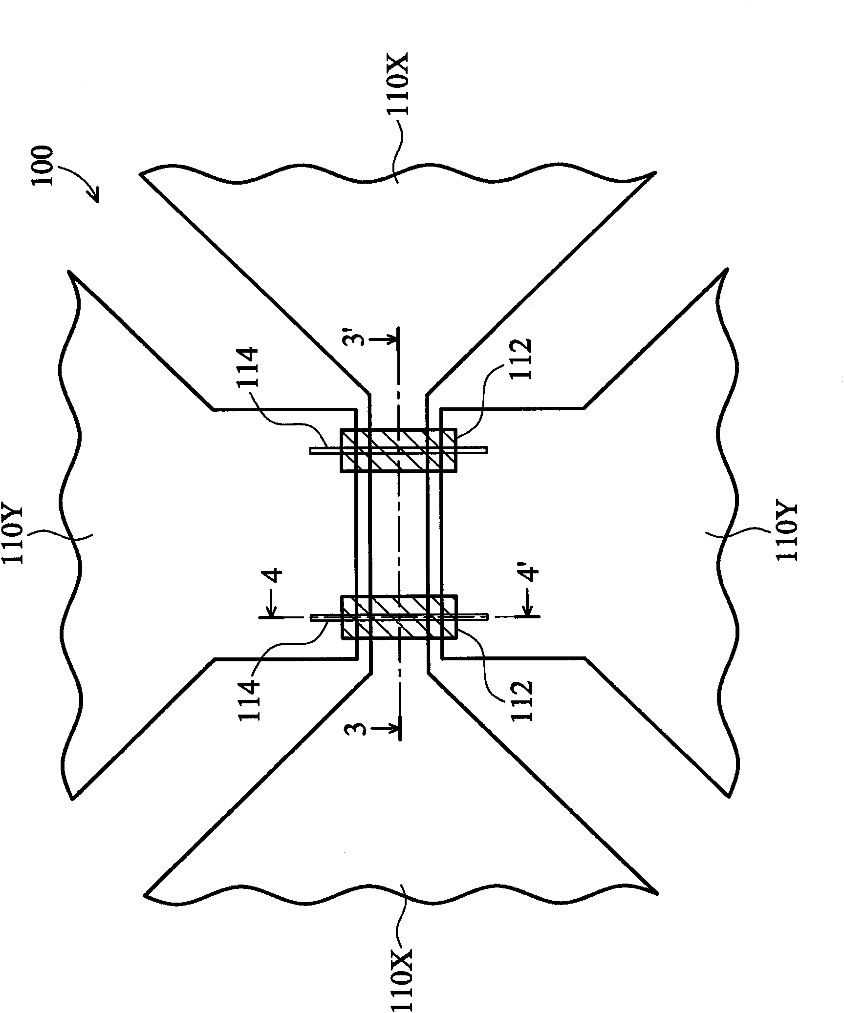
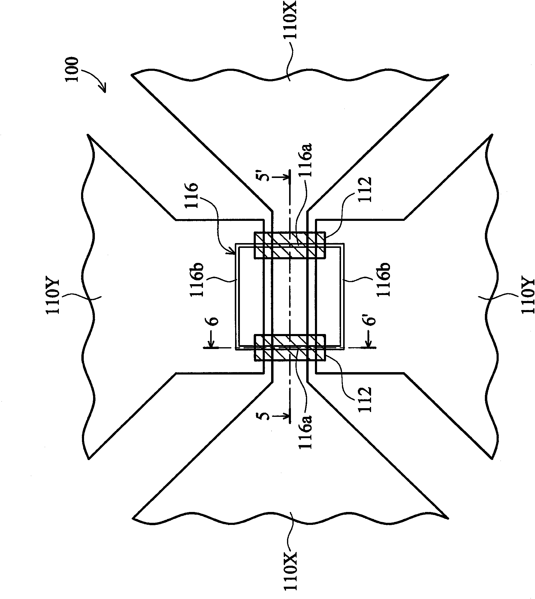
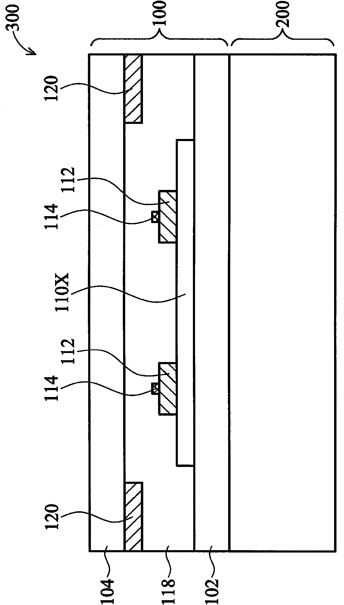
[0022] An embodiment of the present invention provides a touch display device, which includes a touch panel disposed on the display panel, the touch panel includes a capacitive touch element, and the capacitive touch element includes a plurality of first conductive patterns arranged in rows, and A plurality of second conductive patterns arranged in columns, these first conductive patterns and the second conductive patterns are arranged in the same layer structure, in order to avoid short circuit at the intersection of the first conductive pattern and the second conductive pattern, in one embodiment The first conductive patterns arranged in a row are separated from each other, and any two adjacent first conductive patterns are electrically connected through a conductive bridging structure. In addition, an isolation structure is provided between the conductive bridging structure and the connecting portion between any two adjacent second conductive patterns, so as to electrically ...


PUM


Abstract

A touch display device is provided. The touch display device includes a touch panel disposed on a display panel. The touch panel includes a plurality of first conductive patterns arranged along a first direction, wherein the first conductive patterns are separated from each other. A plurality of second conductive patterns is arranged along a second direction perpendicular to the first direction, wherein the second conductive patterns are connected with each other. An isolation structure is disposed between any two adjacent first conductive patterns. A plurality of conductive bridge structures is disposed on the isolation structure for electrically connecting any two adjacent first conductive patterns.

Description

technical field [0001] The present invention relates to a touch display device, in particular to a structural design of a touch element of a capacitive touch panel. Background technique [0002] The current capacitive touch panel can be divided into two types, one is the add-on touch panel, which adds the touch panel to the outside of the display panel, and the add-on touch panel needs to be composed of two glass substrates. One of the glass substrates is used to make a capacitive touch sensor (touch sensor) on it, and the other glass substrate is used as a protective cover (cover lens) for the capacitive touch sensor. The other is a touch panel on a glass substrate (on glass type), which manufactures a capacitive touch element (touch sensor) on a protective cover (cover lens) of the touch panel, and then connects the touch panel with the display panels combined. [0003] Whether it is an add-on type or a capacitive touch panel on a glass substrate, the bridge structure of...

Claims


Application Information

Patent Timeline
Patent Type & Authority Applications(China)
IPC IPC(8): G06F3/044
CPCG06F2203/04111G06F3/044G06F3/0446G06F3/0443
Inventor 詹建廷阮一中李国胜叶长青林松君
Owner HANNSTAR DISPLAY CORPORATION
Why Eureka
Try Eureka