Low power consumption operation for active RFID (Radio Frequency Identification) system

An operating method and low-power technology, applied in the field of radio frequency identification, can solve the problems of increasing cost, increasing circuit complexity, increasing the cost of active tags, etc., to achieve the effect of extending service life and reducing average power consumption

Inactive Publication Date: 2012-12-19
UNIV OF ELECTRONIC SCI & TECH OF CHINA
View PDF4 Cites 12 Cited by
  • Summary
  • Abstract
  • Description
  • Claims
  • Application Information

AI Technical Summary

Problems solved by technology

For example, an active RFID device that achieves ultra-low standby power consumption through a passive wake-up method, through the design of a passive wake-up module, is used to receive and detect the wake-up signal of the reader, thereby controlling the power on and off of the active tag, Achieve the goal of achieving low power consumption; however, the newly added passive wake-up module not only increases the cost of the active tag, but also increases the complexity of the circuit
Another example is an active RFID system with a wake-up function, which sets the active tag to cycle between the working area and the non-working area, and uses the excitation source to control when the tag returns data to the reader; the same as the previous scheme Similarly, additional excitation sources not only increase the complexity of the active RFID system, but also increase the cost
Another example is a method for continuously uploading information with low power consumption in a microwave band active RFID system, which utilizes the method of dividing time slots to enable active tags to upload data in designated time slots, while in other time slots it is in low power consumption, thereby Realize low-power information upload; however, it needs to be kept in the electromagnetic wave wake-up state. Obviously, in this state, the energy consumption cannot be ignored

Method used


Image

  • Low power consumption operation for active RFID (Radio Frequency Identification) system
  • Low power consumption operation for active RFID (Radio Frequency Identification) system
  • Low power consumption operation for active RFID (Radio Frequency Identification) system

Examples


Embodiment Construction

[0018] The present invention will be further described below in conjunction with the accompanying drawings and specific embodiments.

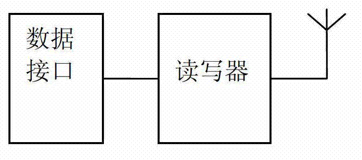
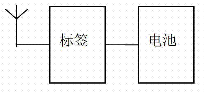
[0019] Such as figure 1 , figure 2 As shown, a typical active RFID system on which the method of the present invention relies is mainly composed of two parts: a reader-writer unit and an active tag unit. The reader starts the operation of the active tag by the command sent by the upper computer (such as PC) through the data interface. The active tag is powered by the battery, and the two units communicate wirelessly through the antenna.

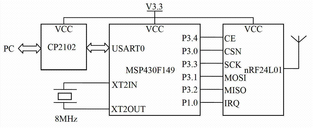
[0020] Such as Figure 1a , Figure 2a shown in figure 1 with figure 2 A specific embodiment of an active RFID system based on the principle, in this specific embodiment, the active RFID system mainly includes two parts: a reader unit and an active tag unit. The structural block diagram of the reader unit is as follows Figure 1a , mainly consists of controller MSP430F149 and 2.4GHz wireless transceiv...


PUM


Abstract

The invention relates to a low power consumption operation for an active RFID (Radio Frequency Identification) system, which is appropriate for the active RFID system including a reader-writer unit and an active label unit, wherein the reader-writer unit starts the operation on the active label unit through an order sent by a data interface by an upper computer; after the reader-writer unit is started, the reader-writer unit takes T1 as a period so as to send N orders to the active label unit continuously; in each T1 period, the reader-writer unit is immediately switched to a receiving state after sending the data so as to wait for the response data returned by the label; until to the T1 time, the reader-writer unit is switched to a sending mode so as to send the data again; and then the reader-writer unit is switched to the receiving state after sending the data; and such circulation is carried out until to N times. The beneficial effects of the method are that the purpose for reducing the average power consumption of the active label is achieved and the service life of the active label is greatly prolonged.

Description

technical field [0001] The invention belongs to the technical field of radio frequency identification, and in particular relates to an energy consumption control technology of an active radio frequency identification system. Background technique [0002] Radio Frequency Identification (RFID) technology is a communication technology that identifies specific targets and reads and writes relevant data through radio signals without establishing mechanical or optical contact between the identification system and specific targets. As a high-tech and information standardization basis for fast, real-time, and accurate collection and processing of information, it has been recognized as one of the important technologies in the world, and has broad application prospects in various industries such as production, retail, logistics, and transportation. Radio frequency identification technology has gradually become an indispensable technical tool and means for enterprises to improve the ma...

Claims


Application Information

Patent Timeline
IPC IPC(8): G06K17/00
Inventor 周华王鲁豫吕洪光龚光珍吴君常伟
Owner UNIV OF ELECTRONIC SCI & TECH OF CHINA
Why Eureka
Try Eureka