Method and circuit for eliminating errors and duty ratio detection circuit
An error elimination and circuit technology, applied in the field of circuits, can solve problems such as duty cycle error and measurement error
- Summary
- Abstract
- Description
- Claims
- Application Information
AI Technical Summary
Problems solved by technology
Method used
Image

Examples
Embodiment 1
[0074] see Figure 7 , which is a schematic structural diagram of the first error elimination circuit provided by the embodiment of the present invention, the circuit includes:
[0075] Compensation phase shifting module 701 and counting control module 702;
[0076] The quantization signal acts on an input end of the compensation phase shifting module 701, the sampling signal acts on the other input end of the compensation phase shifting module 701, and the output end of the compensation phase shifting module 701 is connected to the input end of the counting control module 702;
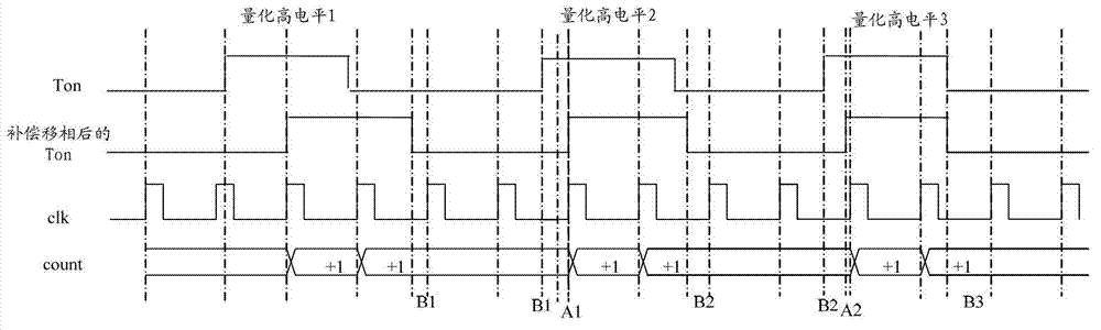
[0077] The compensation phase shifting module 701 sequentially shifts the phases of each quantized high level in the current set of quantized high levels, so that the rising edge of each phase-shifted quantized high level is synchronized with the rising edge of the sampling signal, and each phase shifted The length of the final quantized high level is an integer multiple of the sampling signal period...
Embodiment 2
[0088] When i is equal to 1, the error elimination circuit is as follows.
[0089] see Figure 8, is a schematic structural diagram of a second error elimination circuit provided by an embodiment of the present invention, the circuit includes: a capacitor C, a charging and discharging module 801, a judging module 802, and a counting control module 702, wherein:
[0090] One end of the capacitor C is grounded, and the other end is connected to the output terminal of the charging and discharging module 801 and the input terminal of the judgment module 802 respectively; The output terminal of 802 is connected to the input terminal of the counting control module 702; the sampling signal clk acts on the control terminal of the judging module 802 and the control terminal of the counting control module 803 respectively.
[0091] It works as follows:
[0092] When the first rising edge of the quantized signal Ton arrives (when the rising edge of the quantized high level 1 arrives), ...
Embodiment 3
[0126] When i is greater than 1, the error elimination circuit is as follows.
[0127] The embodiment of the present invention also provides a third error elimination circuit, which includes:
[0128] Capacitor C, charging and discharging module 1301, judging module 1302 and counting control module 702, wherein:
[0129] One end of the capacitor C is grounded, and the other end is connected to the output terminal of the charging and discharging module 1301 and the input terminal of the judgment module 1302; The output terminal of 1302 is connected to the input terminal of the counting control module 702; the sampling signal clk acts on the control terminal of the judgment module 1302 and the control terminal of the counting control module 702 respectively.
[0130] The rising edge of the quantized high level after the compensation phase shift is the moment when the capacitor C stops charging, and the falling edge of the quantized high level after the compensation phase shift ...
PUM
 Abstract
Description
Claims
Application Information
 - R&D Engineer
- R&D Manager
- IP Professional
- Industry Leading Data Capabilities
- Powerful AI technology
- Patent DNA Extraction
Browse by: Latest US Patents, China's latest patents, Technical Efficacy Thesaurus, Application Domain, Technology Topic.
© 2024 PatSnap. All rights reserved.Legal|Privacy policy|Modern Slavery Act Transparency Statement|Sitemap