Antenna provided with cover radiator

A technology of radiators and antennas, applied to antenna equipment, antennas, resonant antennas with additional functions, etc., can solve problems such as long distances, and achieve the effect of small size

Active Publication Date: 2012-12-19
PULSE FINLAND
View PDF3 Cites 7 Cited by
  • Summary
  • Abstract
  • Description
  • Claims
  • Application Information

AI Technical Summary

Problems solved by technology

However, the solution in Fig. 1 has the disadvantage that good band characteristics and sufficient efficiency require a significantly long distance between the radiator and the ground plane GND

Method used


Image

  • Antenna provided with cover radiator
  • Antenna provided with cover radiator
  • Antenna provided with cover radiator

Examples


Embodiment Construction

[0016] Figure 1 has been described in conjunction with the description of the prior art.

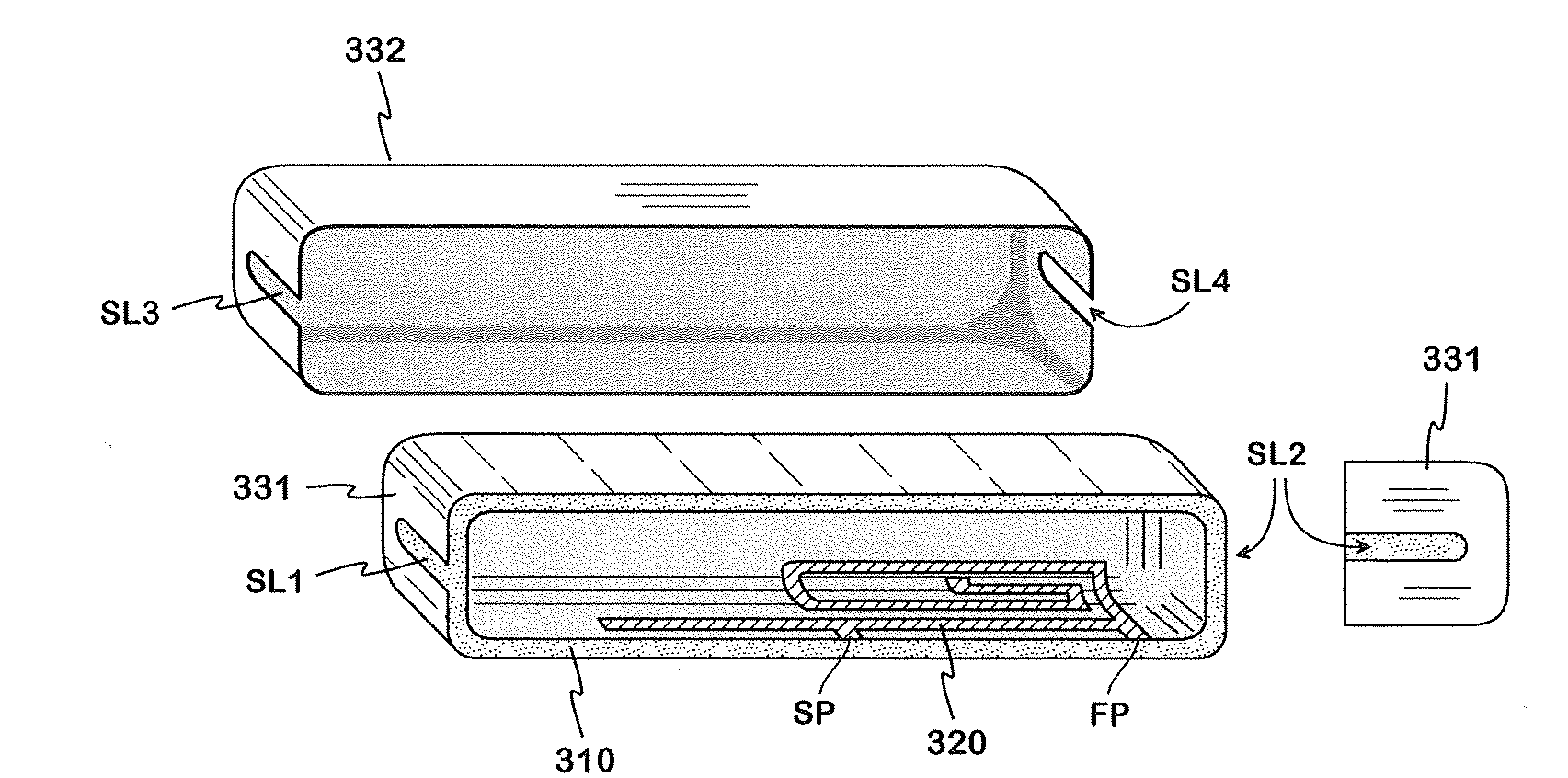
[0017] figure 2 An example of a radio device with an antenna according to the invention is shown. The radio device RD is elongated and relatively flat such that it has two ends, a head surface corresponding to these ends, a front and a rear surface and first and second side surfaces. The antenna radiator is located at one end of the device, which may be the end on the speaker side of the device, or the opposite end. In the figure is seen the housing of the device, comprising the main body COV of the housing and the radome 332 . In this example, the radome has a conductive material, for which reason it functions as part of the radiating structure. The radiator is just below it. Also, in this example the body COV of the cover is of conductive material, for which reason there is a relatively narrow non-conductive portion SPL of the cover between it and the radome 332 .

[0018] The rad...


PUM


Abstract

A monopole antenna applicable especially to small mobile stations. The radiator (331) of the antenna is trough-like so that it covers the head surface, front and rear surfaces and both side surfaces of the dielectric cover (310) of the radio device at an end of the device. On the side of the side surfaces there are slots (SL1, SL2) in the radiator starting from its edge for increasing the electric size. The radiator is fed electromagnetically by a separate element (320) which is shaped so that the antenna has at least two operating bands. The ground plane of the antenna is apart from the radiator, thus not extending inside the 'trough'.

Description

technical field [0001] The invention relates to a monopole antenna, the radiator of which conforms in shape to the housing of the device, which antenna is especially suitable for small mobile stations. Background technique [0002] In small-sized radio equipment such as mobile phones, the pursuit of space saving is a constant factor in designing the equipment. Regarding the antenna, i.e. using a dielectric substrate of the radiator, the above mentioned implementation using a monopole radiator instead of the radiator in the PIFA (Planar Inverted-F Antenna) and the housing of the radio is a space saving solution . [0003] It is likewise known to make radiators part of the housing of the device. An example of such an arrangement is the solution for an antenna of a radio device shown in FIG. 1 , which is known from publication EP1439603. The radio device and its section at the antenna structure can be seen from behind. The upper part 130 of the rear part of the housing of t...

Claims


Application Information

Patent Timeline
Patent Type & Authority Applications(China)
IPC IPC(8): H01Q1/24H01Q9/04H01Q1/44H01Q5/01H01Q5/10H01Q5/357H01Q5/378
CPCH01Q9/0421H01Q1/42H01Q9/42H01Q5/0051H01Q1/243H01Q5/0062H01Q5/357H01Q5/378H01Q1/44H01Q9/0457H01Q1/241
Inventor H.科瓦
Owner PULSE FINLAND
Why Eureka
Try Eureka