Eureka AIR delivers breakthrough ideas for toughest innovation challenges, trusted by R&D personnel around the world.

Polyphase AC motor, driving device and driving method therefor

a technology of ac motor and ac motor, which is applied in the direction of motor/generator/converter stopper, dynamo-electric converter control, magnetic circuit shape/form/construction, etc., can solve the problems of increasing the number of times of measurement and analytical operation, and increasing the length in the axial direction. , to achieve the effect of increasing the length in the axial direction and increasing the size of the electric motor

Inactive Publication Date: 2014-03-04
HITACHI LTD
View PDF17 Cites 2 Cited by
  • Summary
  • Abstract
  • Description
  • Claims
  • Application Information

AI Technical Summary

Benefits of technology

[0009]A problem of the prior art is that by the means for realizing magnetic insulation between the phases, the length in the axial direction is increased and as a result, the size of the electric motor is increased.
[0018]According to the preferred embodiments of the present invention, without increasing the size of the electric motor and using a complicated torque pulsation calculating means, by approaching from a control side, a pulsation reduction can be realized.
[0019]As a concrete method, a command value of generating an alternating current for reducing pulsations is expressed by a simple formula and is incorporated in the control, thus the magnetic flux pulsations of the secondary electric angle, furthermore the torque pulsations of the same order can be reduced.

Problems solved by technology

A problem of the prior art is that by the means for realizing magnetic insulation between the phases, the length in the axial direction is increased and as a result, the size of the electric motor is increased.
Further, the means for calculating the torque pulsations beforehand by the torque pulsation calculating means and adding the waveform of the opposite phase to the command value is difficult in the calculation of torque pulsations, increases in the number of times of measurement and analytical operation, thereby becomes complicated.

Method used


Image

  • Polyphase AC motor, driving device and driving method therefor
  • Polyphase AC motor, driving device and driving method therefor
  • Polyphase AC motor, driving device and driving method therefor

Examples


first embodiment

[0037](First Embodiment)

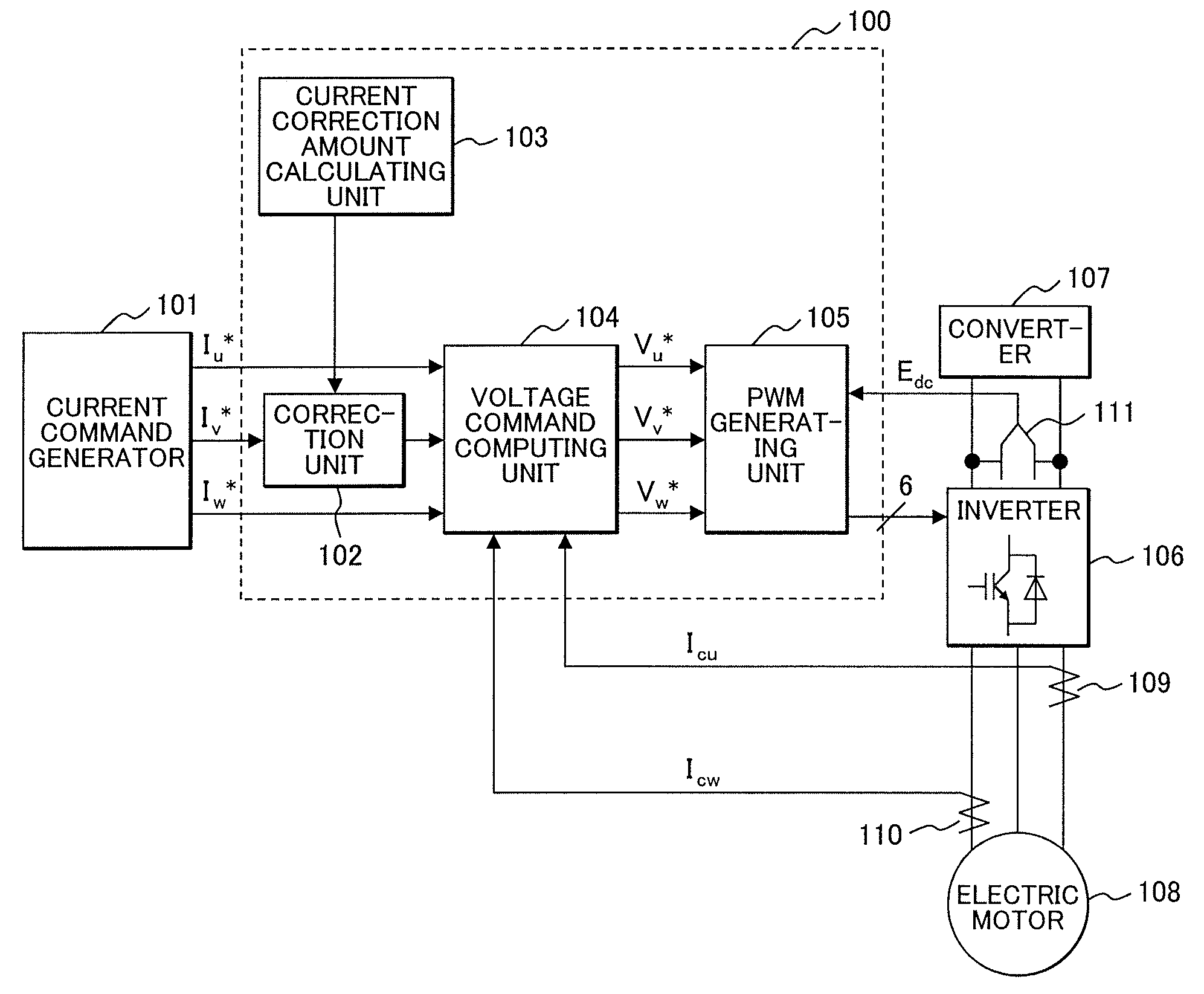
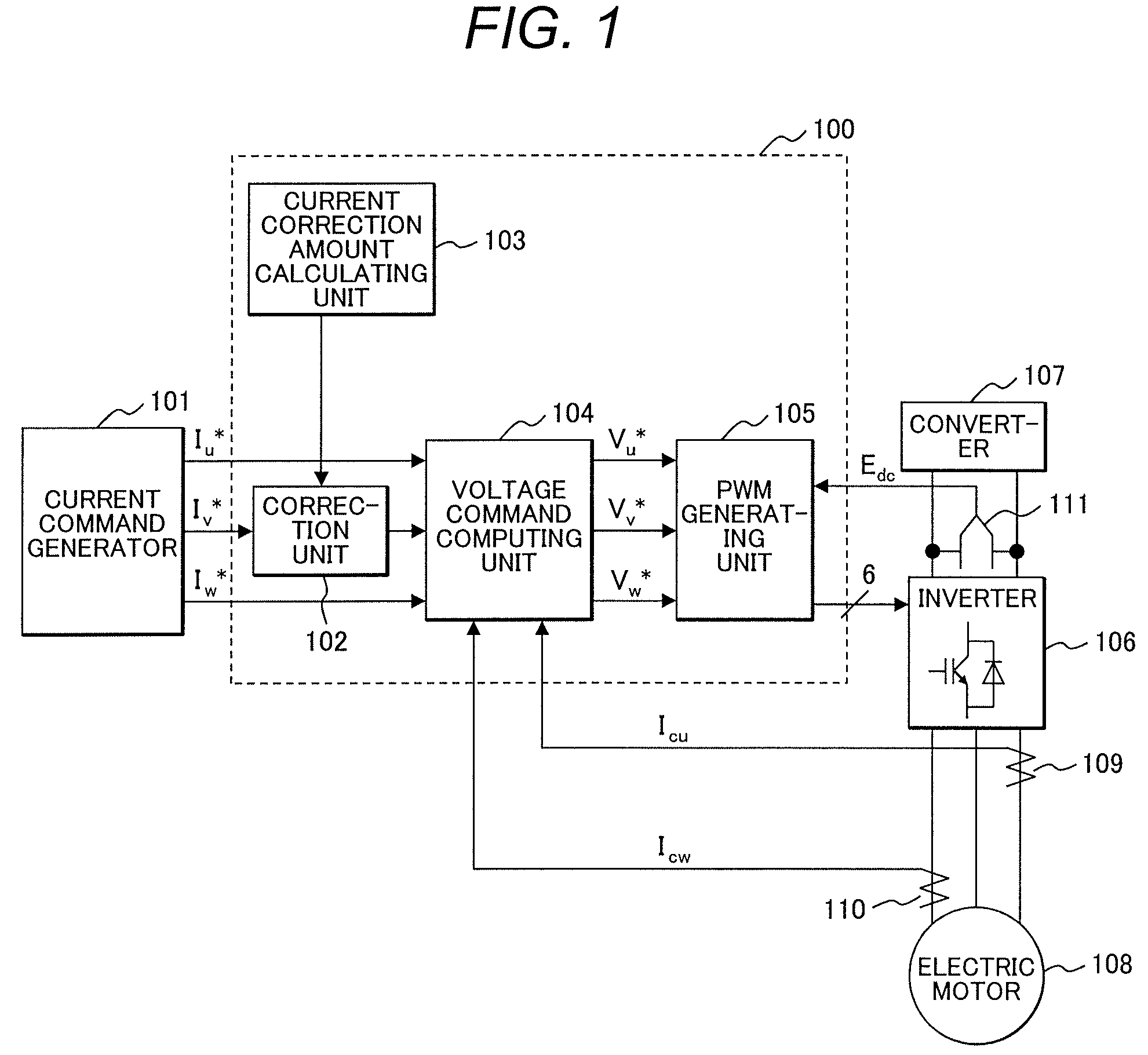
[0038]FIG. 1 is a block diagram showing the system constitution of the first embodiment of the driving device of the polyphase AC motor of the present invention. The controller of the driving device of the first embodiment includes a current command generator (101) for generating a command value of a current to be fed to the electric motor and a control unit (100) for generating a pulse width modulation signal (hereinafter, abbreviated to a PWM signal) from the current command value. The main circuit includes an inverter (106) driven by the PWM signal, a converter (107) for feeding a DC voltage to the inverter (106), and a claw-teeth type motor (108) to be controlled. Further as auxiliary devices for control, U-phase and V-phase current detectors (109) and (110) for detecting U-phase and V-phase currents fed to the claw-teeth type motor (108) from the inverter (106) and a voltage detector for detecting an input voltage Edc of the inverter (106) are included.

[...

second embodiment

[0055](Second Embodiment)

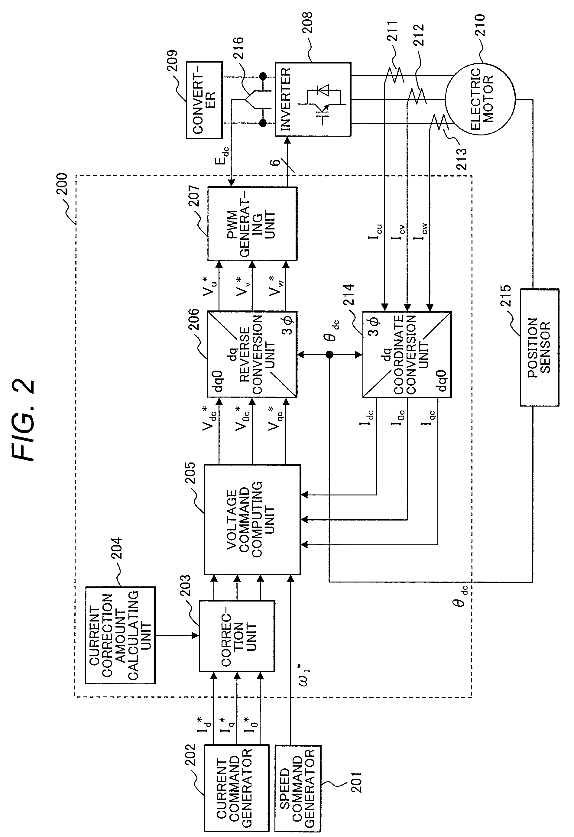
[0056]FIG. 2 is a block diagram showing the system constitution of the second embodiment of the driving device of the polyphase AC motor of the present invention. The controller of the driving device of the second embodiment includes a speed command generator (201) for generating a speed command value for deciding the speed of the rotor of the electric motor, a current command generator (202) for generating current command values of the d-axis, q-axis, and 0-phase, and a control unit (200) for adjusting a PWM signal from the command value. As a main circuit, a converter (209) for feeding a DC voltage to an inverter (208), the inverter (208) driven by the PWM signal, and a claw-teeth type motor (210) to be controlled are included. Further, as auxiliary devices for control, U-phase to W-phase current detectors (211) to (213) for detecting U-phase to W-phase currents fed to the electric motor (210) from the inverter (208), a position sensor (215) for detecting ...

third embodiment

[0074](Third Embodiment)

[0075]FIG. 3 is a block diagram showing the system constitution of the third embodiment of the driving device of the polyphase AC motor of the present invention. The controller of the driving device of the third embodiment includes a current command generator (301) for generating current command values of the d-axis and q-axis, a speed command generator (302) for generating a speed command value, and a control unit (300) for adjusting a PWM signal from the command value. As a main circuit, a converter (309) for feeding a DC voltage to an inverter (308), the inverter (308) driven by the PWM signal, and a claw-teeth type motor (310) to be controlled are included. Further, as auxiliary devices for control, U-phase and W-phase current detectors (311) and (312) for detecting U-phase and W-phase currents fed to the electric motor (310) from the inverter (308), a position sensor (314) for detecting the position of the electric motor in rotation, and a voltage detect...


PUM


Abstract

Provided is an AC motor in a three-phase unbalanced state such as a claw-teeth type AC motor (108), which is reduced in magnetic flux pulsations and torque pulsations. Among the current command values of individual phases to be intrinsically given to an inverter (106) for feeding three-phase alternating currents of variable voltages / frequencies to the electric motor, a current command of an intermediate phase (a V-phase) having a smaller magnetic resistance of a stator core than those of other phases is subjected to a reducing correction by a correction unit (102) on the basis of the correction amount calculated by a current correction amount calculating unit (103), and the unbalanced three-phase alternating currents are fed to the AC motor (108), so that magnetic flux pulsations of a secondary electric angle and torque pulsations of the same order are reduced.

Description

FIELD OF THE INVENTION[0001]The present invention relates to a polyphase AC motor in an unbalanced state and a driving device and a driving method therefor.BACKGROUND OF THE INVENTION[0002]The polyphase AC motor, particularly a permanent magnet synchronous motor is extended in the range of applicable uses to household electric appliances, industries, motorcars, etc. by utilizing the characteristics such as a small size and high efficiency. Particularly in recent years, electric motors having a driving system changed from the square wave power supply type to the sine wave power supply type are increased and controllers requiring the input of electric constant set values of an electric motor such as resistance, inductance, and induced voltage constant for uses of rotor position inference under the position sensorless control and high precision torque control are increased. Therefore, unless the electric constants of the electric motor are identified and input accurately, the control p...

Claims


Application Information

Patent Timeline
Patent Type & Authority Patents(United States)
IPC IPC(8): H02K29/06H02K1/14H02K21/14H02P6/06H02P6/08H02P6/10H02P6/17H02P6/28H02P21/00H02P21/22H02P23/16H02P25/026H02P27/04H02P27/08
CPCH02P6/10H02P27/08H02K37/14H02K21/14H02K1/145H02P21/00
Inventor IWASAKI, NORIHISANAKATSUGAWA, JUNNOSUKEIWAJI, YOSHITAKA
Owner HITACHI LTD
Why Eureka
Eureka Blog
Learn More